


17
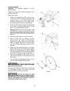
2. Loosen the bevel lock handle (A, Fig. 8) and tilt
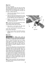
the cutting arm completely to the left (Figure 11).
3. Using a combination square, check to see if the
blade is 45° to the table.
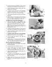
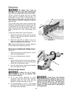
4. To adjust, tilt the cutting arm to zero degrees,
loosen the lock nut (B, Fig. 12) and turn the
stop bolt (A, Fig. 12) in or out accordingly.
5. Tilt the cutting arm back to the left and recheck
alignment.
6. Repeat steps 1–4 if necessary until the blade is
45° to the table, then tighten the lock nut (B,
Fig. 12) to secure the stop bolt (A, Fig. 12).
45° Right Bevel Positive Stop Adjustment
1. Set the miter angle to zero degrees. Fully
extend the sliding fence completely to the right
then pull the bevel detent pin (E, Fig. 12) out.
Note: When retracting the bevel detent pin, it
may be required to slightly shift the upper arm
assembly right or left.
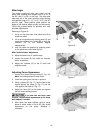
2. Loosen the bevel lock handle (A, Fig. 8) and tilt
the cutting arm completely to the right (Figure 13).
3. Using a combination square, check to see if the
blade is 45° to the table.
4. To adjust, tilt the cutting arm to zero degrees,
loosen the locknut (D, Fig. 12) and turn the
stop bolt (C, Fig. 12) in or out accordingly.
5. Tilt the cutting arm back to the right and
recheck alignment.
6. Repeat steps 1–4 if necessary until the blade is
45° to the table, then tighten the lock nut (D,
Fig. 12) to secure the stop bolt (C, Fig. 12).
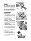
33.9° Left & Right Bevel Adjustment
1. Set the miter angle to zero degree. Fully extend
both sliding fences.
2. Loosen the bevel lock handle (A, Fig. 8).
3. Tilt the cutting arm to the 33.9° left bevel
position and engage the positive stop by
pushing the bevel detent pin (E, Fig. 12) in.
4. Using a combination square, check to see if the
blade is 33.9° to the table.
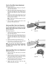
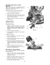
5. To adjust, turn the setscrew (A, Fig. 14) in or
out with a 6mm hex wrench until the blade is
33.9° to the table.
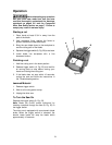
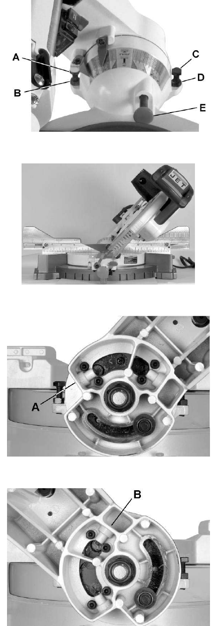
6. Repeat steps for the right bevel 33.9º bevel
adjustment, making adjustments to setscrew B,
Fig. 15.
Figure 12
Figure 13
Figure 14
Figure 15