19
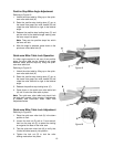
Positive Stop Miter Angle Adjustment
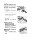
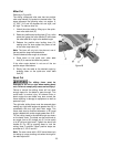
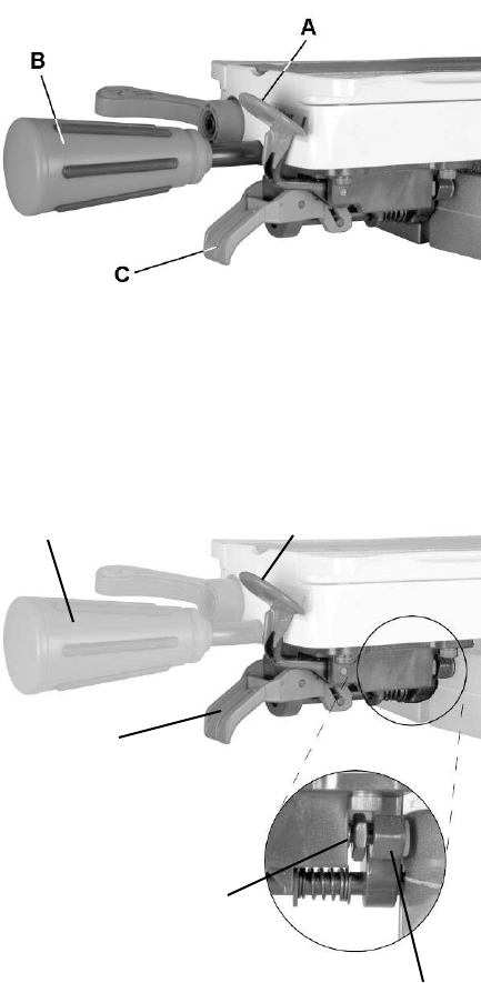
Referring to Figure 19:
1. Unlock the miter table by lifting up on the quick-
cam miter table lock (A).
2. Raise the positive stop locking lever (C) up; at
the same time grasp the miter handle (B) and
rotate the miter table left or right to the desired
angle.
3. Release the positive stop locking lever (C) and
set the miter at the desired angle making sure
the lever snaps into place.
Note: There are ten positive stops into which
the lever will lock.
4. After the angle is selected, press down on the
quick-cam miter table lock (A).
Quick-cam Miter Table Lock Operation
If a miter angle required is not one of ten positive
stops, the miter table can be locked at any angle
between these positive stops by using the quick-
cam miter table lock.
Referring to Figure 19:
1. Unlock the miter table by lifting up on the quick-
cam miter table lock (A).
2. Raise the positive stop locking lever (C) up; at
the same time grasp the miter handle (B) and
rotate the miter table left or right to the desired
angle.
3. Release the positive stop locking lever (C).
4. Press down on the quick-cam miter table lock
(A) until it locks the miter table in place.
Note: The quick-cam miter table lock should lock
the table and prevent it from moving. If adjustment
is needed, see Quick-cam Miter Table Lock
Adjustment below.
Quick-cam Miter Table Lock Adjustment
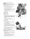
Referring to Figure 20:
1. Place the quick-cam miter lock (A) in the down
position to lock.
2. Loosen the lock nut (D) with a 13 mm wrench,
then turn the stop nut (E) to extend the locking
arm against the base of the miter saw.
3. Test the quick-cam miter lock (A) to verify that
it locks the table securely into position.
4. Tighten the lock nut (D) to lock the miter
locking mechanism into place.
Figure 19
Figure 20
A
B
C
D
E


