


3
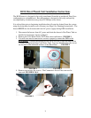
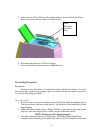
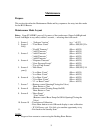
5. On the side of the brewer locate the Connector Cover. Remove and reserve the
screw. Remove the Connector Cover and expose DPK Interface Connector.
FIGURES 5 & 6
FIGURE 5 FIGURE 6
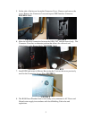
6. Make the electrical connection between the DPK CWT and the brewer body. The
Connector Cover has an alternate position that allows for cable exit and
reattachment to the Brewer Body. FIGURES 7 & 8
FIGURE 7 FIGURE 8
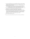
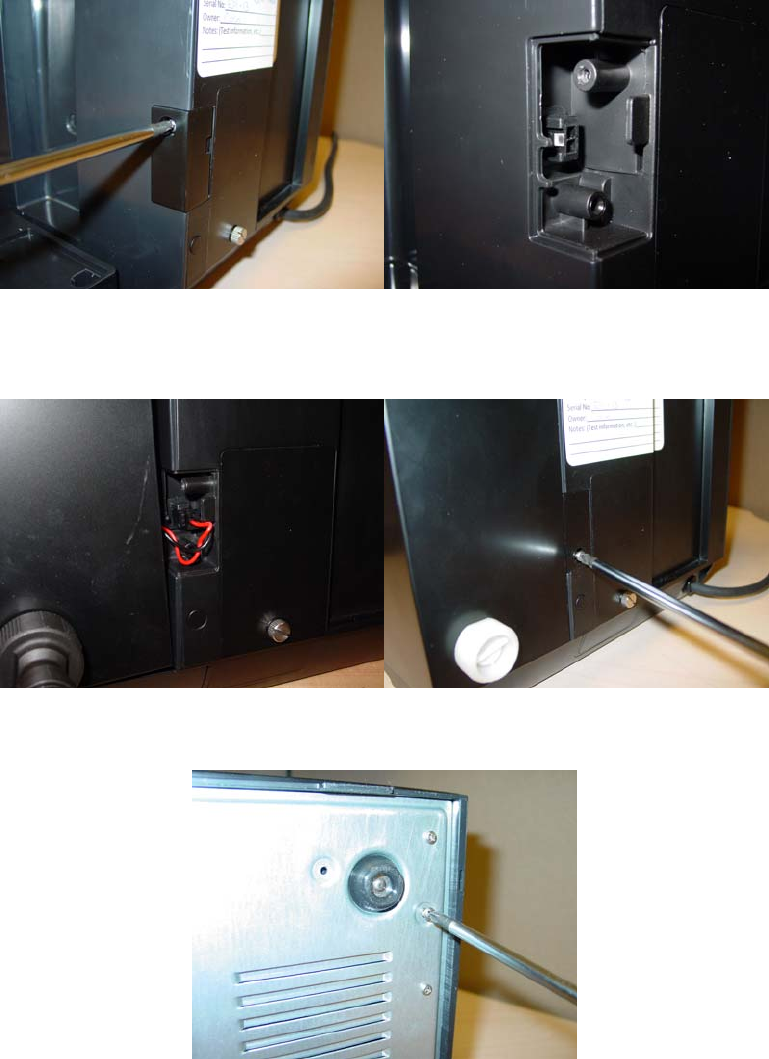
7. Install DPK and secure to Brewer Base using the 2 screws that were previously
used for the Connection Access Plate. FIGURE 9
FIGURE 9
8. The B150 Direct Plumbed Unit is now ready to be connected to AC Power and
filtered water supply in accordance with local Building Code rules and
regulations.