Page 2
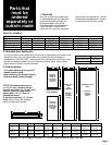
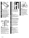
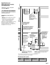
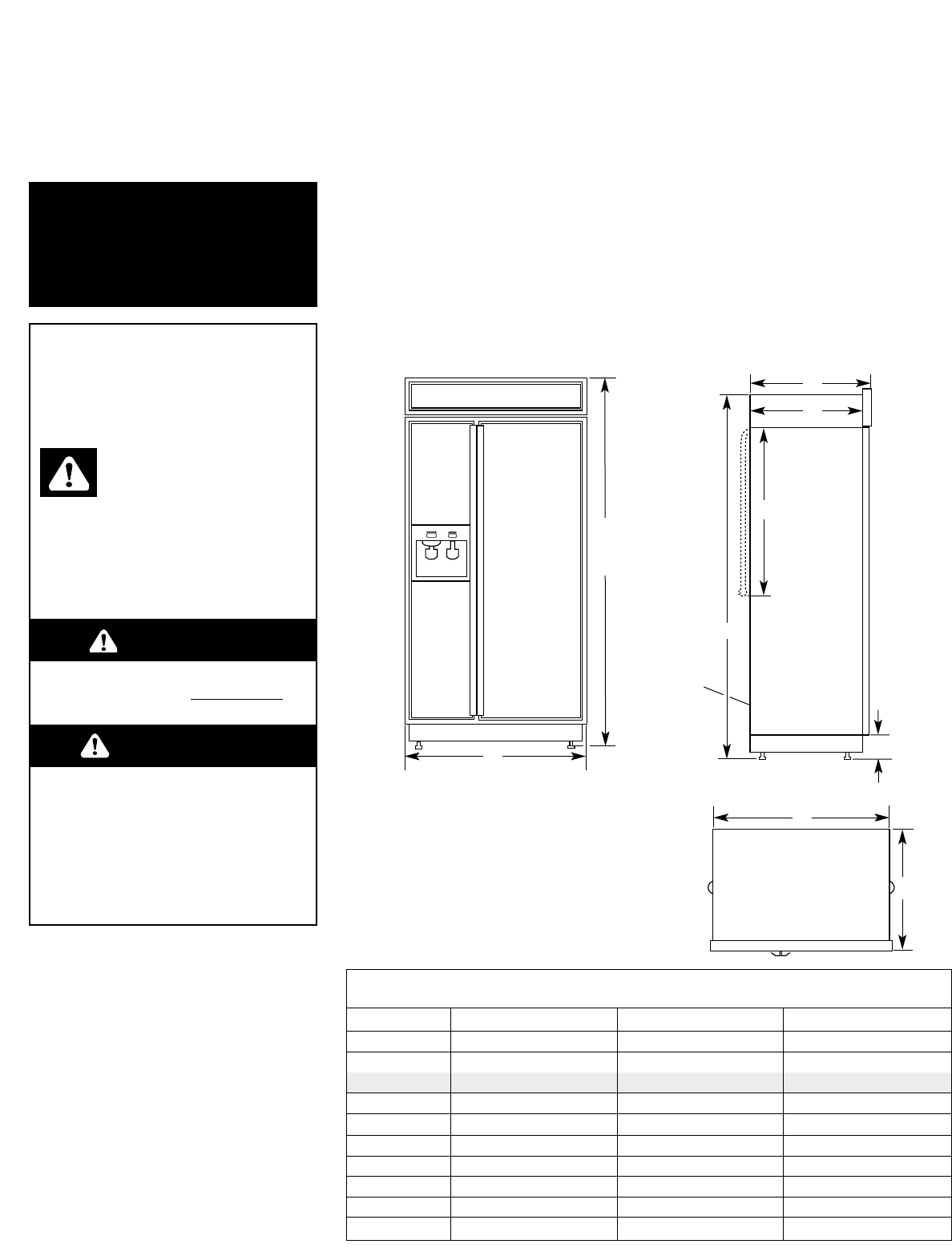
36" (91 cm) 42" (106 cm) 48" (122 cm)
A 36" (91 cm) 42" (106 cm) 48" (122 cm)
B
Panel model
83-5/8" (212 cm)* 83-5/8" (212 cm)* 83-5/8" (212 cm)*
B 83-1/8" (211 cm) 83-1/8" (211 cm) 83-1/8" (211 cm)
C 25-1/8" (64 cm) 25-1/8" (64 cm) 25-1/8" (64 cm)
D 23-1/2" (60 cm) 23-1/2" (60 cm) 23-1/2" (60 cm)
E 3-1/2" (9 cm)* 3-1/2" (9 cm)* 3-1/2" (9 cm)*
F 83-1/8" (211 cm)* 83-1/8" (211 cm)* 83-1/8" (211 cm)*
G 24" (61 cm) 24" (61 cm) 24" (61 cm)
H 35" (89 cm) 41" (104 cm) 47" (119 cm)
I 25" (63.5 cm) 25" (63.5 cm) 25" (63.5 cm)
Before you
start...
Keep cardboard shipping piece or
plywood under refrigerator until it is
installed in the operating position.
Note: If you are using a reverse osmosis
water filtering system, it is recommended
that the refrigerator’s water filter be
removed and the cap be replaced in the
grille. (See Use and Care Guide.)
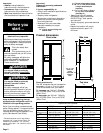
Front view
A
C
D
G
E
F
Product dimensions
* Dimensions shown are for leg levelers
extended 1/8" (3 mm) below rollers. For
levelers fully extended 1-1/4" (32 mm)
below rollers, add 1-1/8" (29 mm) to this
dimension.
Important:
Observe all governing codes and
ordinances.
It is your responsibility to:
• Comply with installation specifications
and dimensions.
• Properly install refrigerator.
• Remove any moldings or decorative
panels that prevent the refrigerator
from being serviced.
• Make sure that you have these
materials necessary for proper
installation:
1/4" (6 mm) copper tubing with
shutoff valve
Panel models only:
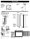
The “B” dimension can be increased or
decreased 1/2 inch (1.3 cm) by using
Grille Kits available from your dealer.
To increase: use “84-inch” Grille Kit
No. 4378788 (Silver Trim) or 4378789
(White Trim).
To decrease: use “83-inch” Grille Kit
No. 4378786 (Silver Trim) or 4378787
(White Trim).
Top view
H
I
Side view
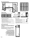
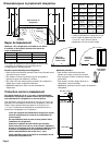
1/4" (6 mm) compression fitting
6 – #8 x 3" (7.6 cm) wood screws
(Longer screws may be
required.)
2 – 2" x 4" x 32" (5 cm x 10 cm x
81 cm) min. wood boards
(See Page 4.)
• Assure that floor will support
refrigerator weight (more than
600 lb/272 kg), door panels,
and contents.
• Provide a properly grounded electrical
outlet.
• Assure that location will permit
appliance doors to open 110°
minimum.
B
See
Note.
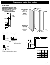
Panel models and wraparound metal door models
Dispenser and Non-Dispenser
Wraparound metal
model
Important:
• Installer: Leave Installation
Instructions with the homeowner.
• Homeowner: Keep Installation
Instructions for future reference.
• Save these Installation Instructions for
the local electrical inspector’s use.
5 ft. (1.5 m)
water line
tubing
coiled and
taped to
back
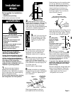
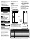
You can be killed or seriously
injured if you don’t follow
instructions.
DANGER
Your safety and the safety of
others are very important.
We have provided many important
safety messages in this manual and
on your appliance. Always read and
obey all safety messages.
All safety messages will tell you
what the potential hazard is, tell you
how to reduce the chance of injury,
and tell you what can happen if the
instructions are not followed.
You can be killed or seriously
injured if you don’t immediately
follow instructions.
WARNING
This is the safety alert
symbol.
This symbol alerts you to
potential hazards that can kill or hurt
you and others.
All safety messages will follow the
safety alert symbol and either the
word “DANGER” or “WARNING”.
These words mean:


