


Electrical
requirements
Before you
start...
Injury Hazard
To eliminate the risk of burns or fire,
avoid installing cabinet storage above
the cooking surface. If cabinets are
already installed, avoid the use of
cabinets while cooktop is in use.
Reaching over a heated cooking
surface could result in a serious burn.
Use two or more people to move and
install downdraft vent.
Failure to follow these instructions can
result in back or other injury.
Important: Observe all governing codes
and ordinances.
Proper installation is your responsibility.
Make sure you have everything necessary
for correct installation. It is the responsibility
of the installer to comply with the installation
clearances specified on the model/serial
rating plate. The model/serial rating plate is
located on the front of the downdraft vent
above the wiring box cover.
Check location where downdraft vent will
be installed. The location should be away
from strong draft areas, such as windows,
doors and strong heating vents or fans.
Before making countertop cutout, check that
downdraft vent and cooktop location will
clear cabinet walls, backsplash, and rear
wall studs inside cabinet.
ALL OPENINGS IN THE WALL OR
FLOOR WHERE RETRACTABLE
DOWNDRAFT VENT IS TO BE
INSTALLED MUST BE SEALED.
Electrical ground is required. See
“Electrical requirements,” Panel B.
When installing retractable downdraft vent,
the cabinet drawer will need to be removed
and the drawer front installed permanently
to cabinet.
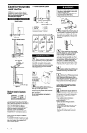
30” min. base cabinet is required. If
cabinet has a drawer, 3-l/2” depth
clearance from the countertop to the top of
the drawer (or other obstruction in the base
cabinet) is required.
Note: Downdraft vent is installed directly
behind the cooktop. Install downdraft vent
first.
Downdraft vent is not approved for use
in mobile homes.
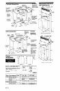
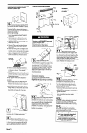
Cabinet construction: Downdraft vent is
designed for use in a cabinet with a depth of
24”. The maximum depth of the overhead
cabinet is 13”. Overhead cabinets installed
at either side of the downdraft vent must be
18” above the cooking surface. See cook-top
Installation Instructions for the minimum
distance between the front edge of the
countertop and front edge of cooktop. The
minimum horizontal distance between the
overhead cabinets is the same as the width
of the installed downdraft vent.
When installing a 36” retractable downdraft
vent with three “Create-A-Cook-top”
modules, the optional support must be
installed on the front of the downdraft vent.
See installation steps for details.
Electrical Shock Hazard
Electrically ground downdraft vent.
Failure to follow this instruction could
result in death, fire or electrical shock.
L
If codes permit and a separate grounding
wire is used, it is recommended that a
qualified electrician determine that the
grounding path is adequate.
Do Not ground to a gas pipe.
Check with a qualified electrician if you are
not sure the downdraft vent is properly
grounded.
Do Not have a fuse in the neutral or
grounding circuit.
IMPORTANT: Save Installation Instructions
for electrical inspector’s use.
Electrical Shock Hazard
Check for electrical wires that may be
concealed behind wall covering before
drilling holes into wall.
Do not use downdraft vent solid state
fan speed control device.
Failure to follow these instructions
could result in death, fire or electrical
Lshock.
It is the customer’s responsibility:
To contact a qualified electrical installer.
To assure that electrical installation is
adequate and in conformance with
National Electrical Code, ANSVNFPA
70 - latest edition*, and local codes
and ordinances.
IA.I
A 120.volt, 60.Hz, AC-only
electrical supply is required on a
separate 15ampere circuit, fused on both
sides of the line. A time-delay fuse or circuit
breaker is recommended. The fuse must be
sized per local codes in accordance with the
electrical rating of the downdraft vent as
specified on the model/serial rating plate
located on the front of the downdraft vent
above the wiring box cover.
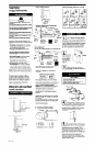
Tools needed for
installation:
8mm or power
318” nut supply
driver or cable
ratchet
le(
THE RETRACTABLE
n
DOWNDRAFT VENT MUST BE
CONNECTED WITH COPPER WIRE ONLY
Ic
. Wire sizes must conform to the
requirements of the National
Electrical Code, ANSIINFPA 70 - latest
edition*, and all local codes and
ordinances. Wire size and connections must
conform with the rating of the downdraft
vent.
Copies of the standard listed above may be
obtained from:
* National Fire Protection Association
Batterymarch Park
Quincy, Massachusetts 02269
sabe
Phillips y
screwdriver
mIm.-YIaYI
screwdriv _.
WARNING -TO REDUCE THE RISK OF
FIRE, ELECTRIC SHOCK, OR INJURY TO
PERSONS, OBSERVE THE FOLLOWING:
A. Installation Work And Electrical
Wiring Must Be Done By Qualified
Person(s) In Accordance With All
Applicable Codes And Standards,
Including Fire-Rated Construction.
B. The combustion airflow needed for
safe operation of fuel-burning
equipment may be affected by this
unit’s operation. Follow the heating
equipment manufacturer’s guideline
and safety standards such as those
published by the National Fire
Protection Association (NFPA), and
the American Society for Heating,
Refrigeration and Air Conditioning
Engineers (ASHRAE), and the local
code authorities.
C. When cutting or drilling into wall or
ceiling, do not damage electrical
wiring and other hidden utilities.
D. Ducted fans must always be vented to
the outdoors.
E. If this unit is to be installed over a tub
or shower, it must be marked as
appropriate for the application.
(DI
This downdraft vent should be
. connected directly to the fused
disconnect (or circuit breaker) through
flexible, armored or non-metallic sheathed,
copper cable. Allow some slack in the cable
so the downdraft vent can be moved if
servicing is ever necessary.
IEl
~ A U.L.-listed, l/2” conduit
connector must be provided at
each end of the power supply cable (at the
downdraft vent and at the junction box).
IFI
.
A wiring diagram is located on the
downdraft vent base above the
wiring box cover.
‘arts supplied
‘or installation:
Electrical connection
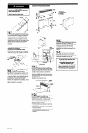
1. Cut a 1 -l/2” hole in floor or side of
cabinet for power supply wire. The hole
cut for electrical wiring through a wood
cabinet should be sanded until smooth.
A grommet (Part No. 302797) must cover
the hole cut for the electrical wiring
through a metal cabinet.
2. Run flexible armored or nonmetallic
sheathed copper cable from fused
disconnect circuit breaker or junction box
through the cabinet hole to the downdraft
vent location.
3. See installation steps to connect power
supply cable to downdraft vent.
l
2 end caps
l
2 lower support legs
l
2 overcounter
mounting brackets
l
2 undercounter
mounting brackets
l
1 bag of fasteners
l
1 metal cover
l
1 backdraft damper
l
literature package
l
optional support and
two screws (36”
models only)
Parts needed
for installation:
Fire Hazard
Do Not obstruct the flow of
combustion and ventilation air.
Failure to follow this instruction could
result in fire.
l
2 conduit connectors
l
1 wall cap for interior-mounted motor
l
ductwork
Panel B