


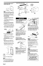

Exterior-mounted
vent motor
9” round ductwork system
Injury Hazard
Use two or more people to move and
install downdraft vent.
Failure to follow this instruction can
result in back or other injury.
NOTE: Exterior-mounted vent motor
installations require exterior blower
system, Part No. KPED890T, available
from your KitchenAid dealer or
authorized parts supplier.
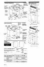
Island location
Maximum length = 55 feet
1 - transition
= 0 feet
2 - 90 elbows
= 10 feet
1 - wall cap
= 0 feet
10 feet straight
= 10 feet
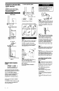
Carefully insert downdraft vent into
Length of 9” system = 20 feet
recommended to support the weight of the
downdraft vent during lifting. Check that
downdraft vent is parallel to side of cutout
and that mounting brackets rest gently on
Recommended standard fittings
::-.
.:.-.-.A..
., ., . . . .
-.:.:
<;;$P=
.; .._ ::..
-
.:::::::::y. ‘7::
j:::::::::::::::::
.:.-.. ..:j:::::::
.,..Q
-
,:;:~:.::~ : j::
,.,.,.,.,.,. .:.:
.;+;;$;:;::z. L’
. . . . _
Figure 6
Built-in cabinet location
countertop.
:::::::zy;::::::>
i -.:.:.:.:.:
-.. .-:::::
-+::o
.:.. -
. . . . . . . . . . . .
..:.:.:..
.:....
3-114” x 14”
to 9” = 4.5 ft.
3-l/4” x 14” to
9” 90” elbow =
5 ft.
9” to 3 1/4”xl4”
90” elbow = 9 ft.
..:.::::: . . . .
--$PT~-
.-.
-:.:.:.. -.:
45” elbow =
2.5 ft.
90” elbow =
5 ft.
9” to 3-114” x
14” = 1 ft.
front of downdraft vent base and
adjust
position of legs until downdraft is level
vertically. Use a pencil to mark the top of
each leg on face of downdraft vent. Then
mark location of support leg mounting holes
on cabinet floor. Remove downdraft vent
from cutout. Drill starter holes at each
mounting screw location on cabinet floor.
Align top of legs with pencil marks on face
of downdraft vent. Tighten screws in legs.
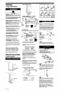
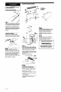
Figure 7
Roof venting
II
’
Place cardboard or another form of
protection on top of a flat surface
where you can easily assemble the
downdraft vent system. Remove parts
packages, downdraft vent and blower box
from carton. Remove all shipping materials,
tape and protective film from downdraft
vent and blower box.
16.1
Attach damper plate (supplied with
exterior blower svstem) to front of
downdraft vent using 4 hex washer nuts.
1
12.1
171
.
Remove the 2 Phillips-head screws
attaching appliance wiring box
cover. Determine which direction (rear or
down) electrical connection will need to run
from appliance wiring box. Remove cover.
Knock out rear or lower wiring opening in
wiring box.
E
3-114”
L 1
Attach one
overcounter
mounting bracket
to each side of
the downdraft
vent with flange
side out.
Power supply cable needed between
exterior blower assembly and blower
box is not provided.
x 14” duct
I
,
b-l
. Attach support legs to side of
downdraft vent with two screws in
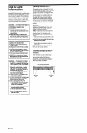
Figure 8
each leg. Do Not tighten screws,
Ductwork may be installed under concrete
slab. See Panel C.
Do not install exterior vent motor in
window well.
Is
Determine the location where the
’ exterior blower box will be located.
Cut opening in roof or wall for ductwork to
exterior blower. Install exterior blower.
Wall Installations
l
Use caulking compound between
mounting flange and wall.
Roof Installations
l
Follow standard roofing procedures.
l
The flashing sheet should be entered over
the roof opening.
l
Lower edge of flashing should lie on top
shingles and upper edge underneath
shingles.
l
Seal assembly between roof, fan and
flashing with roofing mastic to prevent
leaks.
Maximum length of ductwork
system
For best performance, use no more than
three 90” elbows. If more than one elbow is
used, make sure that there is a minimum of
24 inches of straight duct between any two
elbows. Do Not install two elbows
together. It is recommended that you use
round duct instead of rectangular duct,
especially if elbows are required. If
rectangular duct is required, it should be
transitioned to 9” round duct as soon as
possible.
Determining the length of system
you need:
To calculate the length of system you need,
add the equivalent feet for each duct piece
that will be needed. See example for 9”
round ductwork system.
Panel E