


If blower box is removed from vent base,
check that wiring cable is properly
secured in plastic clips.
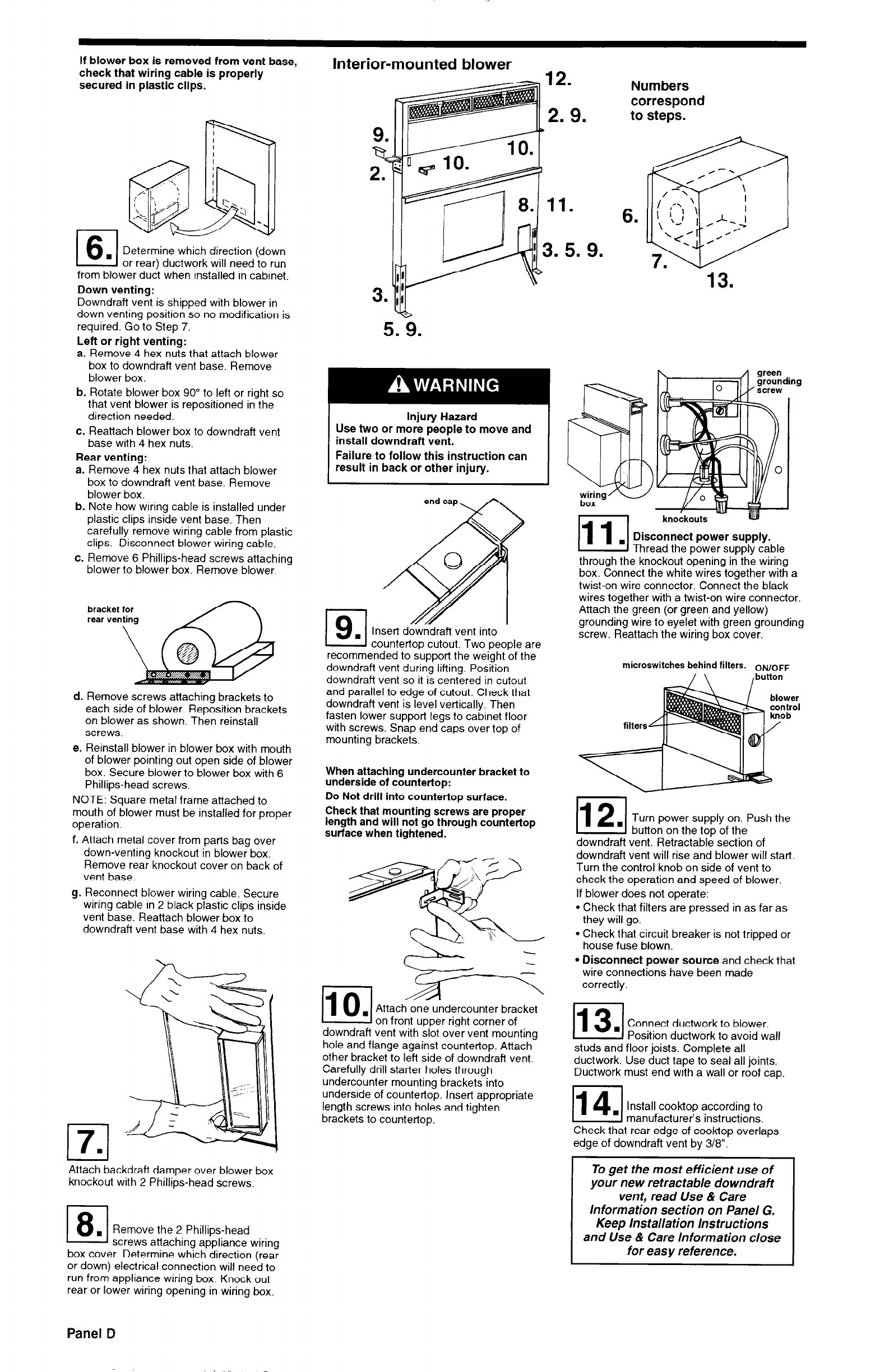
Interior-mounted blower
Numbers
correspond
to steps.
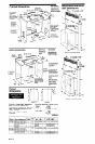
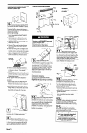
Determine which direction (down
or rear) ductwork will need to run
from blower duct when installed in cabinet.
Down venting:
Downdraft vent is shipped with blower in
down venting position so no modification is
required. Go to Step 7.
Left or right venting:
a. Remove 4 hex nuts that attach blower
box to downdraft vent base. Remove
blower box.
b. Rotate blower box 90” to left or right so
that vent blower is repositioned in the
direction needed.
c. Reattach blower box to downdraft vent
base with 4 hex nuts.
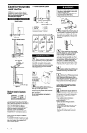
Rear venting:
a. Remove 4 hex nuts that attach blower
box to downdraft vent base. Remove
blower box.
b. Note how wiring cable is installed under
plastic clips inside vent base. Then
carefully remove wiring cable from plastic
clips. Disconnect blower wiring cable.
c. Remove 6 Phillips-head screws attaching
blower to blower box. Remove blower.
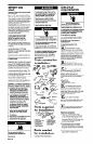
Injury Hazard
Use two or more people to move and
install downdraft vent.
Failure to follow this instruction can
result in back or other injury.
hnr
knockouts
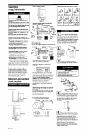
Disconnect power supply.
Thread the power supply cable
through the knockout opening in the wiring
box. Connect the white wires together with a
twist-on wire connector. Connect the black
wires together with a twist-on wire connector.
Attach the green (or green and yellow)
grounding wire to eyelet with green grounding
screw. Reattach the wiring box cover.
bracket for
lg.1
Insert downdraft vent into
countertop cutout. Two people are
recommended to support the weight bf the
downdraft vent during lifting. Position
downdraft vent so it is centered in cutout
and parallel to edge of cutout. Check that
downdraft vent is level vertically. Then
fasten lower support legs to cabinet floor
with screws. Snap end caps over top of
mounting brackets,
microswitches behind filters. ON/OFF
/\
, button
d. Remove screws attaching brackets to
each side of blower. Reposition brackets
on blower as shown. Then reinstall
screws.
e. Reinstall blower in blower box with mouth
of blower pointing out open side of blower
box. Secure blower to blower box with 6
Phillips-head screws.
NOTE: Square metal frame attached to
mouth of blower must be installed for proper
operation.
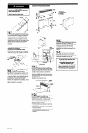
f. Attach metal cover from parts bag over
down-venting knockout in blower box.
Remove rear knockout cover on back of
vent base.
g. Reconnect blower wiring cable. Secure
wiring cable in 2 black plastic clips inside
vent base. Reattach blower box to
downdraft vent base with 4 hex nuts.
When attaching undercounter bracket to
underside of countertop:
Do Not drill into countertop surface.
Check that mounting screws are proper
length and will not go through countertop
surface when tightened.
Turn power supply on. Push the
button on the top of the
downdraft vent. Retractable section of
downdraft vent will rise and blower will start.
Turn the control knob on side of vent to
check the operation and speed of blower.
If blower does not operate:
l
Check that filters are pressed in as far as
they will go.
l
Check that circuit breaker is not tripped or
house fuse blown.
l
Disconnect power source and check that
wire connections have been made
on front upper right corner of
downdraft vent with slot over vent mounting
hole and flange against countertop. Attach
other bracket to left side of downdraft vent.
Carefully drill starter holes through
undercounter mounting brackets into
underside of countertop. Insert appropriate
length screws into holes and tighten
brackets to countertop.
correctly
Connect ductwork to blower.
Position ductwork to avoid wall
studs and floor joists. Complete all
ductwork. Use duct tape to seal all joints.
Ductwork must end with a wall or roof cap.
Install cook-top according to
manufacturer’s instructions.
Check that rear edge of cook-top overlaps
edge of downdraft vent by 3/8”.
To get the most efficient use of
your new retractable downdraft
vent, read Use & Care
Information section on Panel G.
Keep Installation Instructions
and Use & Care Information close
for easy reference.
17.1
I I
Attach backdraft damper over blower box
knockout with 2 Phillips-head screws.
1 8.1 Remove the 2 Phillips-head
r
1 screws attaching appliance wiring
box cover. Determine which direction (rear
or down) electrical connection will need to
run from appliance wiring box. Knock out
rear or lower wiring opening in wiring box.
Panel D