


FOR THE PLUMBER
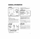
CONNECT TO WATER
(observe local codes)
1
Usa U” (6.35 mm) OD soft copper tubing lor the
cold water supply.
2 Prowde a convement manual shut-oil valve I” the
water llrw
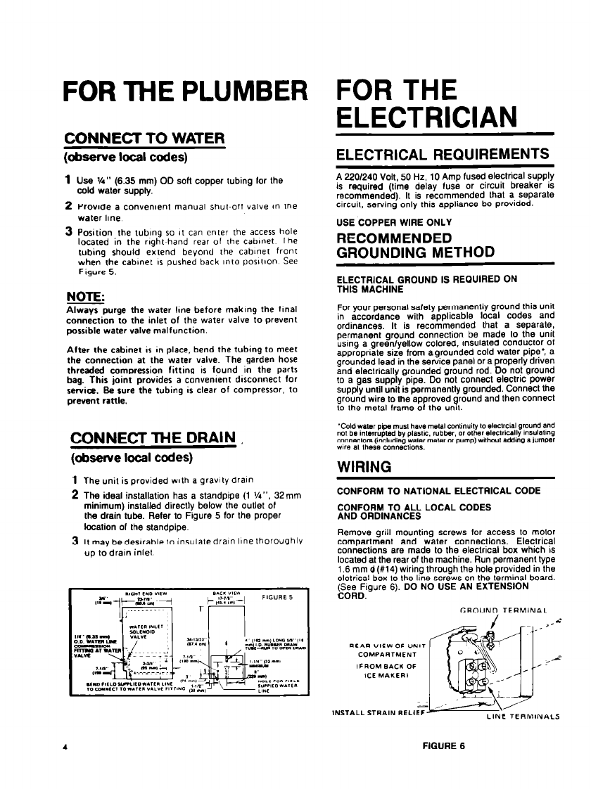
3 Position the rubmg so it can enter the access hole
located in the rmht hand rear of rhe cabinet The
tubing should eitend beyond the cabinet fronr
when the cabinet IS pushed back unto posft~on See
Figure 5.
NOTE:
Always purge the water lme before maklng the final
connection to the inlet of the water valve to prevent
possible water valve malfunction
Alter the cabinet II in place, bend the tubing to meet
the connection at the water valve. The garden hose
threaded compression fitting II found in the parts
bag. This joint provides a conventent dlrconnect for
service. Sa sure the tubing is clear of compressor. to
prevent rattle.
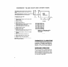
CONNECT ME DRAIN
(observe locel codes)
The unit is provided wth a gravity drain
The ideal installation has a standpipe (1 %“. 32mm
minimum) installed directly below the outlet or
the drain lube. Refer lo Figure 5 (or the proper
location of the standpipe.
It may bedeslrable to insulate drain line thoroughly
up lo drain inlet
4
FOR THE
ELECTRICIAN
ELECTRICAL REQUIREMENTS
A 220/240 Volt, 50 Hz. 10 Amp (used electrical supply
is required (lime delay luse or circuit breaker is
recommended). It is recommended lhat a Separate
clrcuil, serving only this appliance be provided.
USE COPPER WIRE ONLY
RECOMMENDED
GROUNDING METHOD
ELECTRICAL GROUND IS REGUIRED ON
THIS MACHINE
For your personal salety permanently ground this unit
in accordance with applicable local codes and
ordinances. It is recommended that a separate,
permanent ground connection be made lo the unit
using a green/yellow colored, insulated conductor ol
appropriate size from agrounded cold waler pip?: a
grounded lead in the service panel or a properly driven
and electrically grounded ground rod. Do not ground
lo a gas supply pipe. Do not connect electric power
supply until unit is permanently grounded. Connect the
ground wire lo the approved ground and then connect
lo the metal frame 01 the unit.
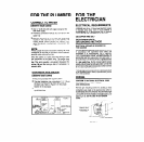
WIRING
CONFORM TO NATIONAL ELECTRICAL CODE
CONFORM TO ALL LOCAL CODES
AND ORDINANCES
Remove grill mounting screws for access to motor
comoartment and waler connections. Electrical
conriections are made lo the electrical box which is
located al the rear or the machine. Run permanent type
1.6 mm d (#14) wiring through the hole provided in the
eletrical box to the line screws on the terminal board.
(See Figure 6). DO NO USE AN EXTENSION
CORD.
GROUND TERMINAL
FIGURE 6