THINGS TO
REMEMBER
0 Water enters only during the defrost cycle. There-
fore the first cycle will be completed without
water in the system.
0 As the room and water temperatures vary. so wll
the amount of Ice produced This means lhat
higher operating temperatures wll reSull In re.
duced ice producllon
0 The unit will shut off when ice in the storage bin
touches the bin thermostat well and 41 auto-
matically cycle to keep the bin full.
0 The storage ban IS nol refngeraled and some
meltage wll occur. This, loo, vanes wth the room
lemperaturd.
0 -The unit needs good aor clrculahon lo perform
efficiently. Keep the front gnll and Ihe condenser
clean.
0 The water syslem. lncludlng filler screen tin lhe
water Inlet solenoid valve. needs lo be cleaned
periodlcally for good cwculahon. Instrucllons are
located on the Inner door panel
OPERATING
INSTRUCTIONS
0 For complete operatmg Informallon, refer to lhe
Use and Care Guide
l Before starling, wash OUI lnlerlor of cablnel with a
Bakmg Soda solution (2 lablespoons soda to a
quan of warm waler) Fllnse thoroughly.
0 Make cenam Ihe waler IS turned on
0 Turn swtch to the “ON” pos~l!on.
IMPORTANT:
Allow
unit
to run lor 3 hour before expectlnp Ice and
for 24 hours bofor. trylng lo eet Ihe lhlcknore
wntml.
If instollod above 2,ooO fwt altitude. SW pa@ 2 for
themlostat adjustments.
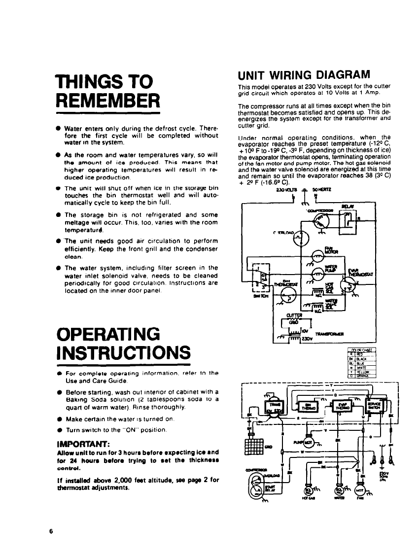
UNIT WIRING DIAGRAM
This model operales al 230 Volts except for the cutter
grid circuit which operates al 10 Volls al 1 Amp.
The compressor runs al all times except when the bin
thermostat becomes satisfied and opens up. This de-
energizes the system except for the transformer and
cutler grid.
Under normal operaling conditions, when the
evaporator reaches the preset lempeialure (-120 C,
+ 1 go F lo -1 Qo C. -30 F. depending on thickness of ice)
the evaporator lhermoslal opens. terminating operation
of Ihe fan motor and pump molar. The hot gas solenoid
and the water valve solenoid are energized al lhis lime
and remain so until the evaporalor reaches 36 (30 C)
+ 2” F (.16.60 C).


