


18
Complete Installation
(Exterior-Mounted Motor)
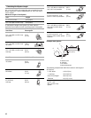
1. Remove 4 screws attaching the terminal box cover.
2. Determine which direction (front or rear) the home power
supply cable and the wiring conduit from the in-line blower
system will enter the terminal box. Remove the appropriate
knockout from the front or rear panel and install two
¹⁄₂" (12.7 mm) UL listed or CSA approved conduit connectors.
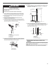
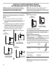
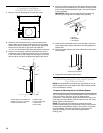
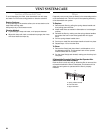
3. Using 2 or more people, insert the downdraft vent into the
countertop cutout. Position downdraft vent so it is centered
in the cutout with the rear flange over the edge of the cutout
and the rear of the vent box against the edge of the cutout.
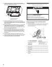
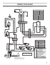
4. Drill 2 pilot holes through each of the undercounter mounting
brackets into the underside of the countertop. Using 2 screws
(not provided) of the appropriate length, mount the brackets
to the countertop.
IMPORTANT: Select a screw length that will not allow the
screws to go through the countertop when tightened.
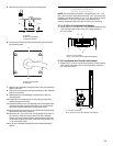
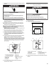
5. Check that the downdraft vent is level vertically. Loosen the
lower support legs screws and position the legs against the
cabinet floor.
6. Fasten the lower support legs to the cabinet floor with screws
(not provided).
7. Tighten the lower support legs screws.
Install Downdraft Vent In-Line (External
Type) Blower Motor
NOTE: Your downdraft vent requires you to purchase an in-line
(external type) blower motor system. See “Blower Motor System”
in the “Accessories” section.
Prepare for Mounting the In-Line Blower System
The in-line blower system must be fastened to a secure structure
of the roof, ceiling, wall, floor, or new or existing frame
construction. The 4 holes on either the inlet (bottom) side or the
outlet (top) side of the blower must be used to mount the in-line
blower system to the structure.
NOTE: The mounting hole locations must span the studs.
Additional stud framing may be required. Plywood may be used
to span open areas between ceiling or floor joists or roof rafters
to aid installation. This structure must be strong enough to
support the weight of the in-line blower system (50 lb
[22.6 kg] min).
A.Terminal box cover
A.Rear flange of downdraft vent
B.Edge of cutout in countertop
C.Rear of downdraft vent
D.Cabinet back
E.Lower support leg
F. Cabinet floor
G.Countertop
A
A
C
B
D
E
F
G
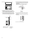
A.Screws
B.Backsplash
C.Countertop
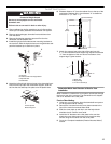
A.Screw (not provided)
A
B
C
A