


9
3. Drill ³⁄₃₂" (2.4 mm) pilot holes for installation into wood. The
screws provided are for mounting the range hood into wood.
Mounting into drywall or plaster is not recommended.
4. Attach each bracket to the wall with 2 - #10 Phillips head
mounting screws. Tighten screws securely.
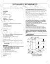
Complete Preparation
1. Determine and make all necessary cuts in the wall for the vent
system. Install the vent system before installing the range
hood. See the “Venting Requirements” section.
2. Determine the location where the power supply cable will be
run through the wall.
NOTE: For wiring flexibility, the terminal box is external to the
range hood motor. About 24" (61.0 cm) of wire connects the
terminal box to the range hood motor.
Check that the lower chimney cover will hide the selected
location.
3. Drill a 1¹⁄₄" (3.2 cm) hole at this location.
4. Pull enough power supply cable through the wall to allow for
easy connection to the terminal box.
Install Range Hood
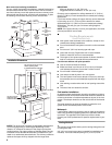
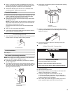
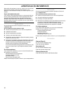
1. Use a flat-blade screwdriver and tighten the 2 leveling screws
located close to the range hood mounting brackets.
Vented Installations
Go to Step 5.
Non-vented (recirculating) Installations
NOTE: Non-vented (recirculating) installation is not allowed over
cooktops with BTU ratings of 60,000 or higher.
2. Install the non-vented (recirculating) conversion kit ordered
for your range hood.
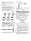
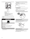
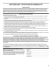
3. Fit the diverter over the vent motor exhaust and push down to
seat. Check that the diverter exhaust outlets are parallel with
the vent motor sides so that they align with the vent cover
openings in the lower chimney.
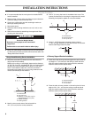
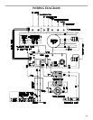
4. Install the 2 vent extension pieces onto the diverter pushing
them until they stop.
5. Using 2 or more people, lift the range hood and place the
mounting hood brackets over the mounting screws. Securely
tighten the screws.
6. Level the range hood. Adjust the 2 leveling screws (see
Step 1) as needed.
Make Electrical Connection
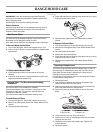
1. Disconnect power.
2. Remove terminal box cover.
3. Remove the knockout in the terminal box and install a UL
listed or CSA approved ¹⁄₂" strain relief.
4. Center the wiring hole in the terminal box over the
1¼" (3.2 cm) diameter wiring hole in the wall. Mark the
2 terminal box mounting holes. Drill ¹⁄₈" (3.0 mm) diameter
holes as needed for your installation.
5. Run 3 wires, black, white and green (or bare), from home
power supply through strain relief into terminal box.
A.Leveling screw
A.Diverter
B.Vent motor exhaust
C.Vent motor
A
A
B
C
A.Diverter
B.Exhaust extension
A
B
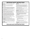
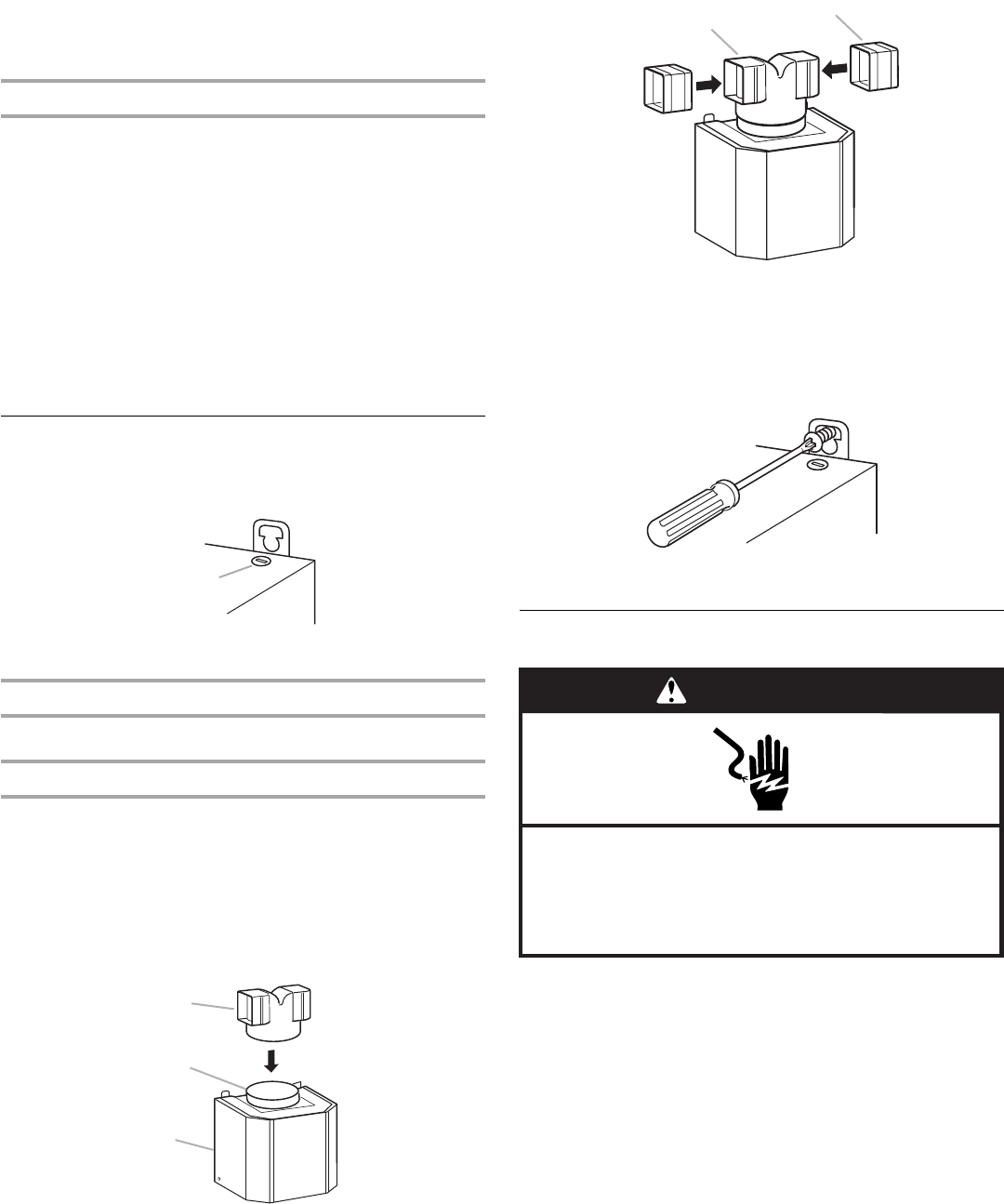
WARNING
Electrical Shock Hazard
Disconnect power before servicing.
Replace all parts and panels before operating.
Failure to do so can result in death or electrical shock.