


15
CONVERSIONS
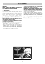
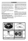
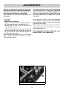
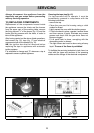
12) REPLACING NOZZLES
The burners can be adapted to suited different
types of gas by fitting the nozzles that correspond to
the gas used. To do this, it is necessary to remove
the burner heads and use a straight key “B”, to
unscrew the nozzle “A” (see fig. 14) and replace it
with a nozzle corresponding to the gas used.
We advise you to block the nozzle tightly.
After making these replacements, the
technician must regulate the burners as
described in paragraph 11, seal any regulation
or pre-regulation organs and apply the label
corresponding to the new gas regulation carried
out on the appliance in place of that previously
applied. This label is contained in the spare
nozzle bag.
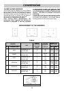
For the ease of the fitter, we have prepared a table
indicating the flow capacities, the heat capacities of
the burners, the diameter of the nozzles and the
working pressure for the various types of gas.
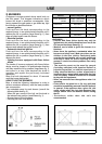
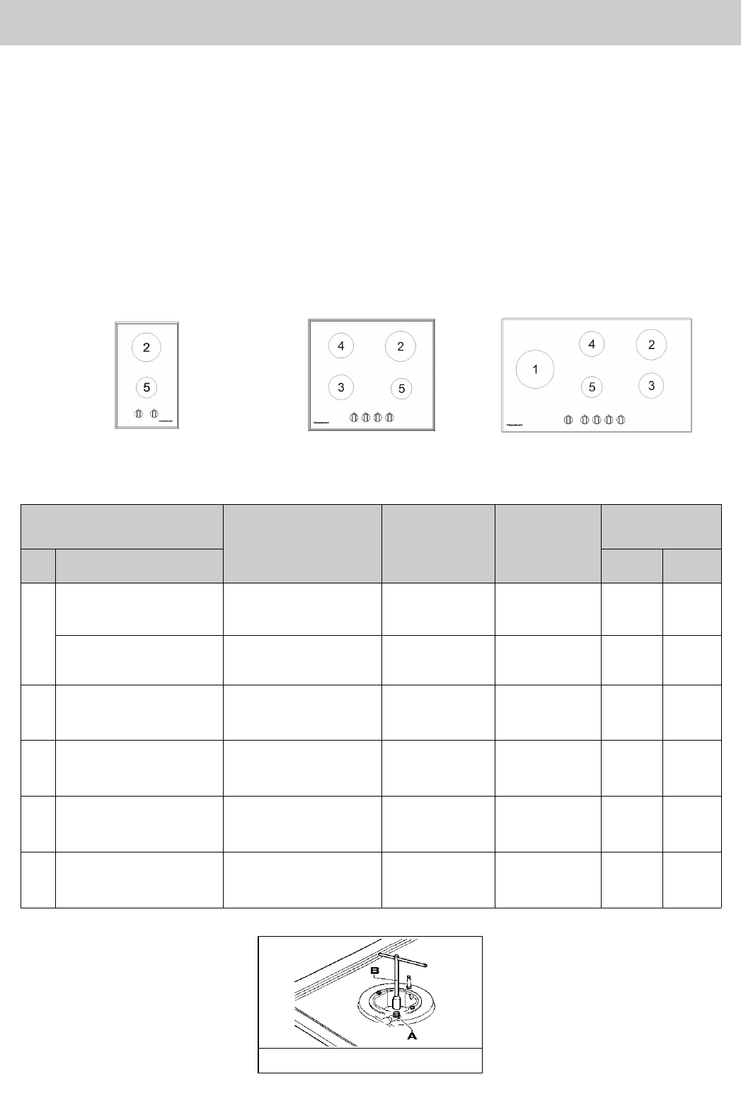
ARRANGEMENT OF THE BURNERS
FIG. 14
BURNERS
GAS
NORMAL
PRESSURE
inches water
column
INJECTOR
DIAMETER
1/100 mm
NOMINAL HEAT
INPUT (B
t
u/h)
N° DESCRIPTION
Min. Max.
1
DUAL
PROPANE HD - 5
NATURAL GAS
11
7
66
125
7800
7800
13000
14500
SIMMER
PROPANE HD - 5
NATURAL GAS
11
7
46 H2
90
1450
2100
2550
3200
2
RAPID
PROPANE HD - 5
NATURAL GAS
11
7
83
145
2400
2400
8350
8350
3
SEMIRAPID
PROPANE HD - 5
NATURAL GAS
11
7
58
100
2050
1700
4350
4350
4
SEMIRAPID
PROPANE HD - 5
NATURAL GAS
11
7
58
100
2050
1700
4350
4350
5
AUXILIARY
PROPANE HD - 5
NATURAL GAS
11
7
50
90
1200
1400
3400
3400
TABLE