


9
INSTALLATION
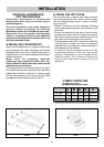
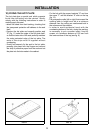
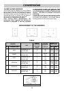
COMPLY WITH THE
DIMENSIONS (in mm)
FIG. 6 FIG. 7
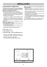
TECHNICAL INFORMATION
FOR THE INSTALLER
Installation, adjustments of controls and
maintenance must only be carried out by a
qualified engineer.
Incorrect installation may cause damage to
persons, animals or property for which the
Manufacturer shall not be considered responsible.
During the life of the system, the automatic
safety or regulating devices on the appliance
may only be modified by the manufacturer or by
his duly authorized dealer.
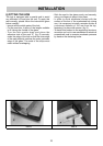
4) INSTALLING THE WORKTOP
Check that the appliance is in a good condition after
having removed the outer packaging and internal
wrappings from around the various loose parts. In
case of doubt, do not use the appliance and contact
qualified personnel.
Never leave the packaging materials
(cardboard, bags, polystyrene foam, nails, etc.)
within children’s reach since they could become
potential sources of danger.
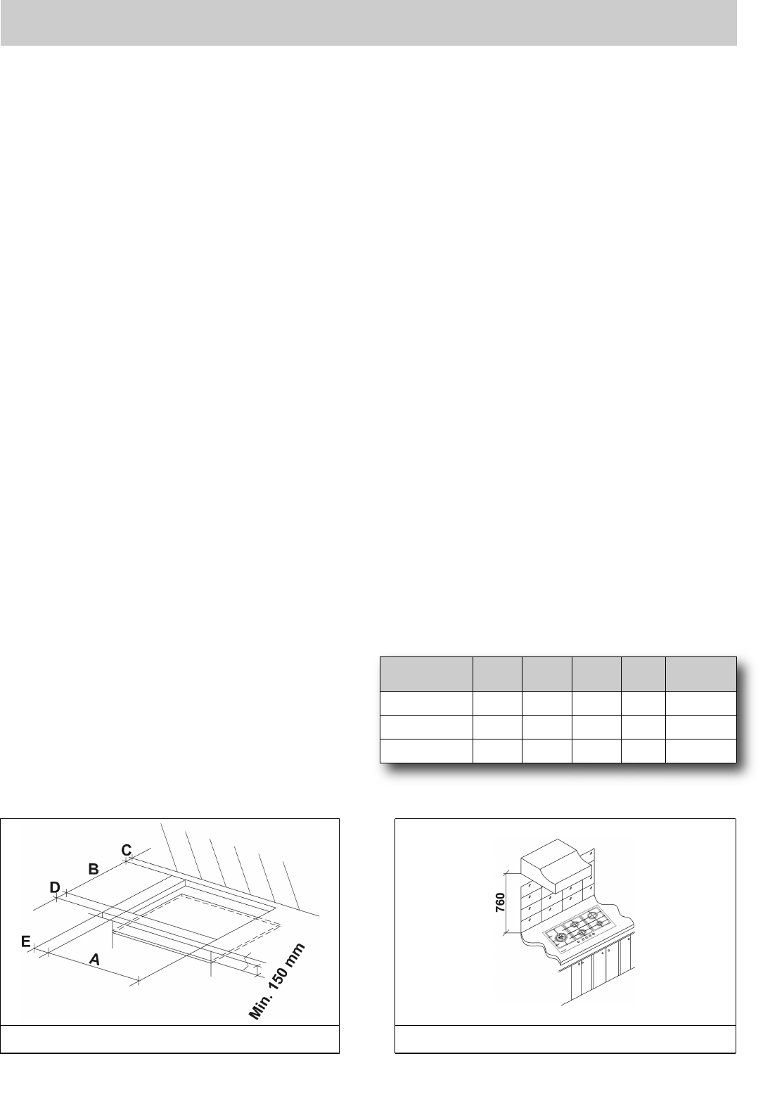
The measurements of the opening made in the top of
the modular cabinet and into which the hot plate will be
installed are indicated in either fig. 6. Always comply
with the measurements given for the hole into which
the appliance will be recessed (see fig. 6 and 7)
.
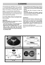
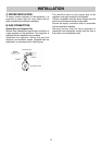
5) FIXING THE HOT PLATE
The hot plate has a special seal which prevents
liquid from getting into the cabinet. Strictly comply
with the following instructions in order to correctly
apply this seal:
- detach the seals from their backing, checking
that the transparent protection still adheres to the
seal itself.
- Evenly and securely fix the seal to the hot plate,
pressing into place with the fingers and remove
the strip of protective paper from the seal and set
the plate into the hole made in the cabinet.
- The prospective walls (left or right) that exceed the
working table in height must be at a minimum
distance from the cutting as mentionned both in
the columns and the scheme.
- In order to avoid accidental touch with the
overheating bottom of the hob, during the
working, is necessary to put a wooden insert,
fixed by screws, at a minimum distance of
150 mm from the lower surface of the top
(see fig. 6).
A B C D E
2F (30) 285 485 57.5 57.5 73 min.
4F (60) 553 473 63.5 63.5 73 min.
5F (90) 833 475 62.5 62.5 73.5 min.