-20-
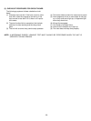
CAUTIONS
1. DISCONNECT THE POWER SUPPLY CORD FROM THE OUTLET WHENEVER REMOVING THE OUTER CASE
FROM THE UNIT. PROCEED WITH THE TEST ONLY AFTER DISCHARGING THE HIGH VOLTAGE CAPACITOR
AND REMOVING THE LEAD WIRES FROM THE INVERTER MODULE.
2. ALL OPERATIONAL CHECKS WITH MICROWAVE ENERGY MUST BE DONE WITH A LOAD (1 LITER OF
WATER IN CONTAINER) IN THE OVEN.
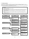
COMPONENTS TEST PROCEDURE RESULTS
INVERTER
(Lead wires removed)
MAGNETRON
(Lead wires removed)
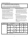
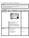
Note: Do not try to repair the inverter board, nor try
to make any adjustments to the board.
Check wiring to the inverter:
1. Unplug the oven’s main power supply.
2. Visually inspect 4 connectors on the inverter
board: CN701, CN702, CN703, E701 to see
whether there are any signs of failure due to
loose wires, bad crimping, sign of overheating,
etc.
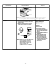
1. Measure the resistance.
(Ohm-meter scale: Rx1)
• Filament terminal
2. Measure the resistance.
(Ohm-meter scale: Rx1000)
• Filament to chassis
Normal: Less than 1 ohm
Normal: Infinite
CN702
CN703
E701
CN701
120V AC
Heat Sink
Control Signal
In/Out
High Voltage
Output to
Magnetron
11. TEST AND CHECKOUT PROCEDURES, AND TROUBLESHOOTING
A. TEST PROCEDURES


