Liebert iCOM Control—Firmware Version XP1.00.010.STD
41
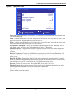
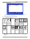
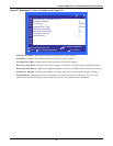
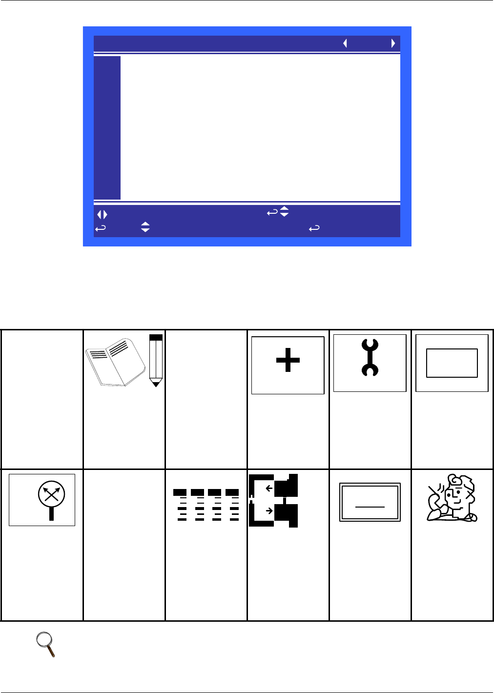
Figure 40 Total Run Hours screen
The parameter shows the actual hours Pump 1 and Pump 2 have operated and the maximum time
Pump 1 can operate before the next maintenance.
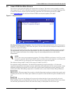
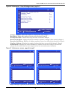
4.9 Liebert iCOM Service Menu Icons and Legend
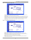
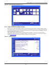
Figure 41 Liebert iCOM Service Menu icons
Setpoints
View and change
operational
setpoints
Unit Diary
Shows all program
changes and
maintenance
performed,
Maintenance/
Wellness
Settings
Shows all mainte-
nance records, cal-
culates next
maintenance date
Diagnostics/
Service Mode
Enter Diagnostics/
Service Mode for
troubleshooting
and repair
Set Alarms
Change settings for
alarms
Sensor
Calibration/Setup
Setup and calibrate
sensors for site
Network
Setup or alter
network setting.
Options Setup
Enter specific
settings for various
options
Smart Module
Setup of alarms
and events. Set
temperature limits
for supply and
return sensors.
Label smart
modules, view
firmware version
Service Contacts
Contains key
contact information
for service
NOTE
Menu shows icons only; text is explanatory and does not appear on the Liebert iCOM display.
TOTAL RUN HOURS
to confirm
for next/previous unit
then
to select parameter
to change parameter
U501
U502
U503
U504
U505
U506
U507
U508
U509
U510
U511
UNIT 01
Actual Hours Limit
Pump 1 454 0
Pump 2 413 0
°C / °F
% RH
SET
WELLNESS
SERVICE
SET
ALARMS
+ / -
NETWORK
SET
UP
XDIO


