


20
GN/SGN/es..6
Instructions for installation and modification
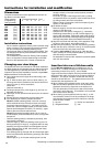
Dimensions
The external dimensions of the appliance can be seen on
fig. S and in the table below.
Gross capacity External dimensions [mm]
of appliance [l] A B C D E F
(see type plate)
162 (18..) 1250 600 631 614 644 1179
200 (21..) 1447 600 631 614 644 1179
238 (25..) 1644 600 631 614 644 1179
276 (28..) 1841 600 631 614 644 1179
188 (20..) 1250 660 683 662 704 1287
233 (24..) 1447 660 683 662 704 1287
279 (29..) 1644 660 683 662 704 1287
324 (33..) 1841 660 683 662 704 1287
Installation instructions
- Do not install the appliance directly next to another refrig-
erator or freezer. This is important to prevent condensa-
tion and consequential damage resulting from it.
- This does not apply to Side-by-Side models (SBS). They
are designed for Side-by-Side installation with another
refrigerator/freezer.
The "Installation instructions for Side-by-Side combina-
tions" are supplied in the accessories bag for the SBS
freezer or the appliance with a freezer compartment.
Changing over door hinges
On appliances which are intended for individual installation
the door hinges can be changed from one side to the other.
On SBS appliances in stainless steel finish, which are de-
signed for Side-by-Side installation, the door hinges must
not be transferred to the other side!
W Only change over door hinges when mains plug is dis-
connected!
W Fig. T. With the door open, lever out plinth panel 1 on
the hinge side with a screwdriver and remove from front.
- Lever out cover 2 with a screwdriver.
Close door.
- Unscrew screw M5 3.
W Pull hinge component 4 with hinge pin 5 out from un-
derneath and remove.
W Open door, lift out at bottom and remove; do not lose the
spacer bl.
W Transfer all hinge components onto the other side:
W Top: depending on version, proceed as follows:
Version I (visible operating panel): Lever out covers 8
with a screwdriver at the front and remove at an angle
from below. Remove hinge pin 7 and insert on the op-
posite side. Use the hexagon socket on the open-ended
spanner provided (spanner width 5). Fit covers 8 again:
insert at rear and click into place at front.
Version II (concealed operating panel): Lift up cover 8
on handle side, push outwards; lift up cover on hinge side
and pull off.
- Unscrew earthing plate cm: first earthing screw cl, then
inner retaining screw cq.
- Unscrew hinge 9: first undo earthing screw cl, then re-
taining screws cq. Fit hinge 9 to opposite side: for easy
assembly, fit hinge from above and first tighten with the
upper retaining screw cq M5, then screw cq and finally
earthing screw cl M4.
- Turn earthing plate cm through 180° and screw tight again
on the new handle side: first retaining screw cq, then earth-
ing screw cl.
- Insert hinge pin 7 in the other retaining hole. Use the
hexagon socket on the open-ended spanner provided
(spanner width 5).
- Fit covers 8 again: insert hinge-side cover by sliding
outwards and click into position; insert handle-side cover
by sliding inwards and click into position.
- Bottom: Using a screwdriver, remove the spacer bo and
replace on the other side.
W Re-attach the door:
- Remove plugs bp from the door mounting points and
replace on the other side.
- Suspend door with spacer in hinge pin 7, close door.
- Rotate hinge component 4 by 180°, remove hinge pin 5,
turn by 180° and replace. Mount both parts in the hinge bq:
slide the pin into the door mounting through the hinge, tilt in
the hinge component, slide up and attach with screw 3.
W Align the door flush with the body of the appliance using
the slot on the hinge bq, then tighten screw 3.
W Attach the plinth panel 1 and click into place by pressing.
W With the door open, insert the cover 2 in the plinth panel
at the front and click into place at the back.
W Transfer* door handle br and plugs bt. With the door
open, carefully lift out the pressure plates* bs at the front
and slide away; unscrew handle.
Re-assemble in reverse order: replace the pressure plates
and click into position.
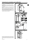
Insertion into row of kitchen units
Fig. U. 600 mm appliances can be installed in a row of
kitchen units. To adapt the height of the appliance to the
surrounding furniture a top unit 1 can be added.
A gap of at least 50 mm depth must be provided behind and
along the entire width of this unit so as to ensure sufficient
ventilation. The area of ventilation underneath the ceiling
should be at least 300 cm
2
. The greater the area the more
economically the appliance will run.
W When installing with standard kitchen units (max. depth
580 mm) and decor panels of max. 2 mm thickness, the
appliance can be set up right next to the kitchen unit.
The door protrudes 34 mm from the side of the kitchen
unit and 51 mm at the front. This enables it to be opened
and closed without difficulty.
W When setting up the appliance next to a wall 4, a mini-
mum distance of 36 mm must be provided on the hinge
side between the appliance and the wall (for the handle
when the door is open).
1 top unit 3 kitchen unit side panel
2 refrigerator/freezer 4 wall
* Depending on model and options