


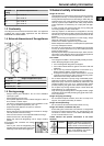
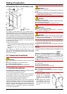
4.2 Insertion into a row of kitchen units
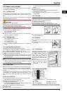
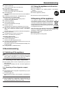
Fig. 9
(1) Stack cabinet (3) Kitchen cabinet
(2) Appliance (4) Wall
The appliance can be inserted into a row of kitchen units. To
match the appliance
Fig. 9 (2)
to the height of the row of units, a
suitable stack cabinet
Fig. 9 (1)
can be fitted above the appliance.
When inserting the appliance into a row of standard kitchen units
(max. depth 580 mm), the appliance can be installed directly next
to the kitchen unit
Fig. 9 (3)
. The appliance door projects relative
to the front of the kitchen unit by 34 mm at the side and by
50 mm in the middle of the appliance. It can be opened and
closed perfectly as a result.
Important for the ventilation:
-
At the back of the stack cabinet there has to be a ventilation
duct of at least 50 mm depth throughout the width of the stack
cabinet.
-
The ventilation space under the ceiling has to be at least
300 cm
2
.
If the appliance is installed with the hinges next to a wall
Fig. 9 (4)
, the distance between appliance and wall has to be at
least 36 mm. This corresponds to the projection of the handle
when the door is open.
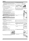
4.3 Transporting the appliance
CAUTION
Risk of injury and danger of damage as a result of incorrect trans-
port!
u
Transport the appliance in a packed condition.
u
Transport the appliance upright.
u
Do not transport the appliance without assistance.
4.4 Installing the appliance
In the event that the appliance is damaged, contact the supplier
immediately before connecting to the mains.
The floor at the site must be flat and level.
Do not install the appliance in a location where it is exposed to
direct radiation of the sun, next to a cooker, heater and similar.
Always install the appliance directly against the wall.
Do not install the appliance without assistance.
Standard EN 378 specifies that the room in which you install your
appliance must have a volume of 1 m
2
per 8 g of R 600a refrig-
erant used in the appliance. If the room in which the appliance is
installed is too small, a flammable gas-air mixture may form in the
event of a leakage in the refrigeration circuit. The quantity of
refrigerant used in your appliance is indicated on the type plate
on the inside of the appliance.
WARNING
Fire hazard due to dampness!
If live parts or the mains lead become damp this may cause short
circuits.
u
The appliance is designed for use in enclosed areas. Do not
operate the appliance outdoors or in areas where it is exposed
to splash water or damp conditions.
WARNING
Fire hazard due to refrigerant!
The refrigerant R 600a is environmentally friendly but flammable.
Escaping refrigerant may ignite.
u
Do not damage the piping of the refrigeration circuit.
WARNING
Fire hazard and danger of damage!
u
Do not place appliances emitting heat e.g. microwaves,
toasters etc. on the appliance!
WARNING
Fire hazard and risk of damage due to blocked ventilation grille!
u
Always keep the ventilation grille free. Always ensure that the
appliance is properly ventilated.
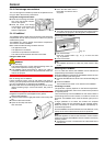
u
Detach the connecting cable from the rear of the appliance,
removing the cable holder at the same time because other-
wise there will be vibratory noise!
u
Remove the protective film from the outside of the appli-
ance.*
NOTICE*
The stainless steel doors are provided with a high-quality surface
coating and must not be treated using the accompanying care
product.
Otherwise the surface coating will be affected.
u
Wipe the coated door surfaces using a soft, clean cloth only.
u
Apply a stainless steel cleaner only to the stainless steel
side walls evenly, wiping with the grain. Subsequent cleaning
becomes easier as a result.
u
Wipe side walls with a paint finish using a soft, clean cloth
only.
u
Remove the protective film from the decorative trims and
drawer fronts.*
u
Remove all transit supports.
u
Dispose of packaging material (see 4.5) .
NOTICE
Risk of damage due to condensate!
u
Do not install the appliance directly alongside a further refrig-
erator/freezer.
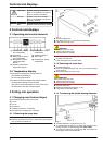
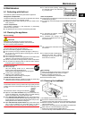
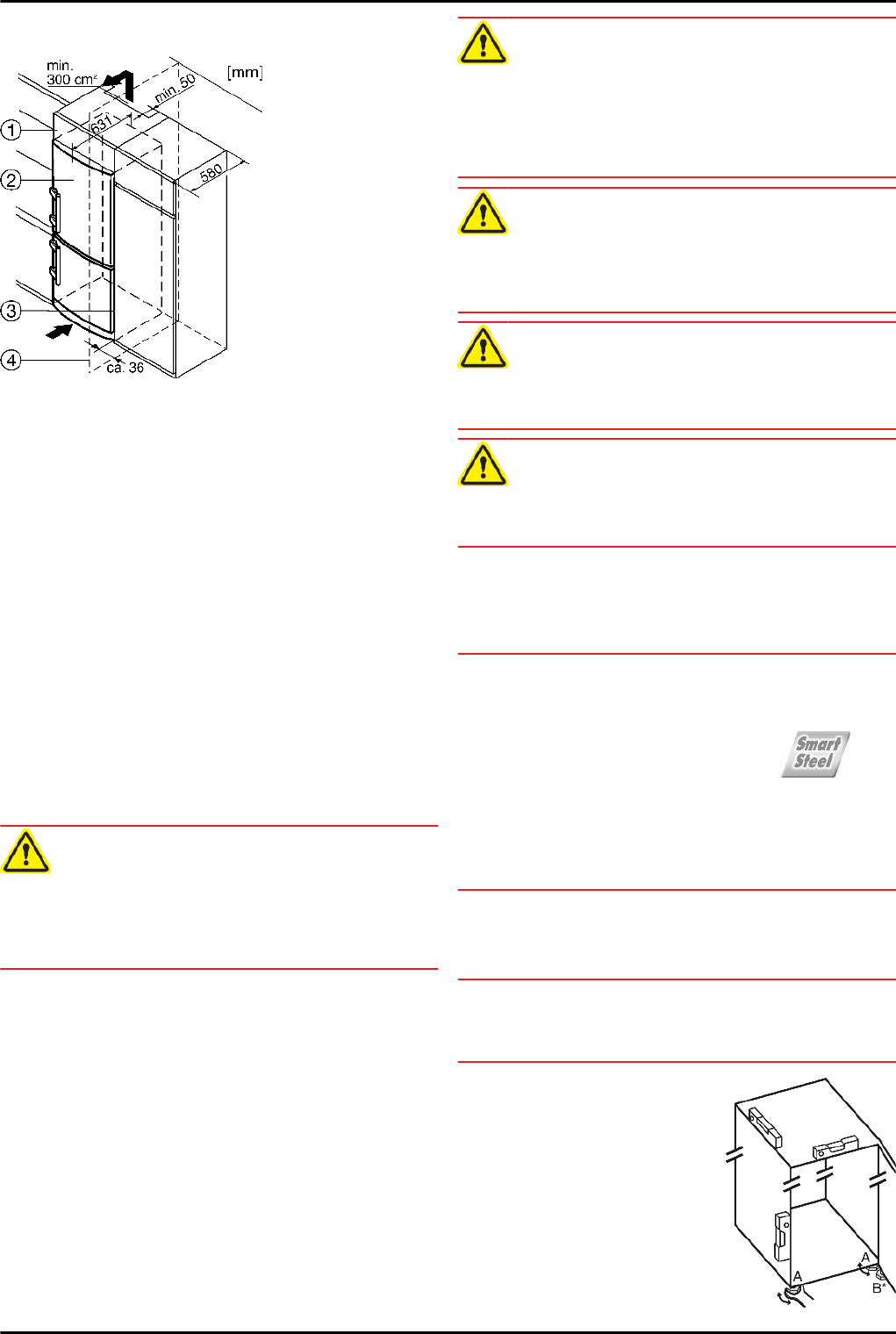
u
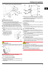
Align the appliance so that it
stands firmly and on a level by
applying the accompanying
spanner to the adjustable-
height feet (A) and using a spirit
level.
u
Then support the door: Extend
the adjustable foot at the turn
hinge (B) until it rests on the
floor and then make a further
90° turn.
Putting into operation
6