Impinger I -–1000 Series Service Manual - Domestic34
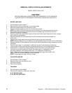
THERMOSTAT, COOLING FAN
1. Shut off power at main breaker.
2. Remove control panel top and front cover.
3. Remove lead wires and mark for reassembly.
4. Remove two (2) screws and remove thermostat.
5. Reassemble in reverse order.
BURNER BLOWER MOTOR
1. Shut off power at main breaker.
2. Remove control panel top and front panel.
NOTE: Complete burner blower motor assembly, with control box (p/n 369359), is no longer
available. The burner blower assembly (p/n 369265) has been changed to a burner motor kit
(p/n 369366). When It is used in the 3 ft Impinger Gas oven, the following modification must be made:
3. Remove control box and components mounted on burner blower motor.
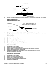
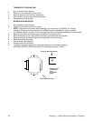
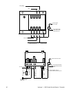
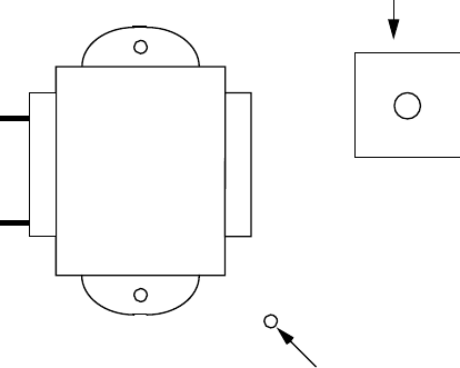
4. Mount transformer on air switch bracket as shown (use transformer as template).
5. Remove three (3) screws that attach blower assembly to burner housing.
6. Mount new blower assembly.
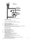
7. Wire as shown. See page 35.
8. Discard control box and relay.
9. Transfer air shutter assembly from old blower assembly to new blower assembly.
MATERIAL NEEDED: #29 drill bit and #8 x 3/8 self tapping screws (3 each)
SEPARATE GROUND SCREW
AIR SWITCH MOUNTING BRACKET
MOUNTING HOLES
(USE #29 DRILL)
#8 X 3/8
SELF TAPPING
SCREW


