Impinger I -–1000 Series Service Manual - Domestic 53
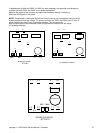
Type IV is 5 5/8 inches wide x 3 ¼ inches deep
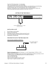
Type IV has adjustment pots. In the center board.
If temperature is still inaccurate after above calibration and troubleshooting, use the following
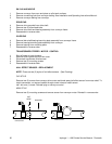
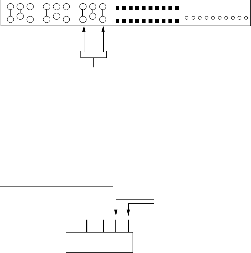
to check the High Temp. Pot. normally the High Temp. Pot. does not require
adjustment. Occasionally the pot is accidentally moved or needs adjustment. Refer to the
following drawing showing proper adjustment of the High Temp. Pot.
test leads here
reading should be 26 ± .5 ohms if not, adjust.
pot. range 0-34 ohms
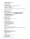
BOTTOM OF TIME TEMP DISPLAY
SWITCH, DISPLAY, SET
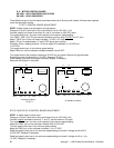
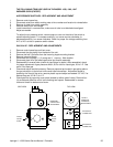
1. Shut off power at main breaker.
2. Remove control panel top.
3. Disconnect wires from time/temp. display terminals 5 and 6.
4. Pull off black operating knob and remove hex mounting nut.
5. Reassemble in reverse order.
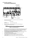
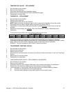
PROCEDURE FOR USE OF TIME/TEMP. SIMULATOR
NOTE: DO NOT CHANGE HI TEMP POT.
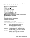
4 7 9 10
TEST PROBES SHOULD
READ 18 OHMS
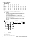
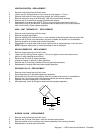
Check incoming power to display at Terminals 1, 2, and 3. Approximately 13 VAC at 1-3, 6.5
VAC at 1-2, 6.5 VAC at 2-3.
WithpowerOFF,removeleadsfrom4,5,6,7,8,9,and10.Installtime/temp.simulator to terminals 4,7,9,10.
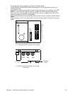
To identify display type: (MEASURE WIDTH OF COVER ON DISPLAY)
Type I is 51/8 inches wide.
Type II is 5 5/8 inches wide.
Type I & II have a 6 position dip switch module.
Type III has a 10 position dip switch module.


