


12
DOOR FRAME HEATER REPLACEMENT
CAUTION: Disconnect main power supply to door of walk-in before beginning the following procedure
to avoid electrical shock.
1. Remove stainless steel raceway from around door opening. Possition raceways away from walk-in to
allow them to warm to room temperature. This will aid in tape adhesion described below. For freezers,
the door power cord must be removed from the light base located on the interior hinge side of the door
frame.
2. Disconnect the heater cable lead wires from the power supply inside the light switch J-box and discard
heater cable.
3. Feed new heater cable lead wires through the opening in the inner frame and secure grommet in the
openning in the back of the ligth switch J-box. Do not connect heater to power supply at this time.
4. Rout heater cable along inside corner of raceway and secure with foil tape. Fasten raceways to door
frame as heater cable is secured in place.
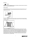
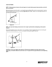
5. Route heater cable along inside bed of sill plate as shown. Note diffeence in routing of cooler and freezer
heater through sill plate. Again, secure heater cable sith foil tape as if is routed. Special care should be
taken not to “kink” heater cable, resulting in improper operation and shortened life of heater. After routing
cable through sill plate, position and fasten threshold plate into place.
6. Fasten heater cable lead wires to power supply in light switch J-box and connect main power supply to
door frame.
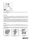
TEMPERATURE CONTROLS
On the CM models, the Temperature Control is on the end penel of the blower housing. These controls have
an “off” position ( at full counter-clockwise position) and should be turned clockwise for “colder”.
On the CL models have an Temperture Control mounted on the front of the Blower housing. The left control is
the Temperature Control and should be turned clockwise for colder. This control does not hae an “off “
position. There is also another control mounted to the right of the Temperature Control. This control is the “
Defrost Termination-Fan Delay Control “ and shuold be preset to the “ 11:00” position. Counter-clockwise
rotation will lengthen defost time; clockwise rotation will decrease defrost time. Turning the knob varies the
defrost termination temperature only and has no effect on the (non-adjustable) fan delay.
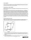
INSTALLING AND OPERATING DIRECTIONS:
Place start pins in outer (24 hours) dial at the time of day that wsitch countacts are to be reverse from shown
when dail pins are opposite time pointer. CAUTION: (Leave at least 1 hole between each adjacent pin).
To set back-up defrost termination:
Push down and rotate pointer on inside (2 hours) dial until it is opposite
desired time.
To set time of the day:
Grasp knob in the outer of the inner (2 hours) dial and rotate it in a counter-clockwise
direction. This will revolve the outer dial. Line up the correct time of day on the outer dial with the time pointer.
Do not try to set the time control by grasping the outer dial. Rotate the inner dial only.
Fro Replacement:
of this control contact Refrigerator manufacture. Master_Bilt (800) 684-8988