


-4-
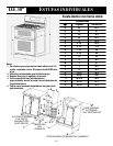
ANTI-TIP DEVICE INSTALLATION INSTRUCTIONS
NOTE: A risk of range tip over exists if the appliance is
not installed in accordance with the provided installation
instructions. The proper use of this device minimizes the
risk of TIP-OVER. In using this device the consumer must
still observe the safety precautions as stated in the USE
and CARE MANUAL and avoid using the oven doors as a
step stool.
Installation instructions are provided for wood and cement
in either floor or wall. Any other type of construction may
require special installation techniques as deemed
necessary to provide adequate fastening of the ANTI-TIP
bracket to the floor or wall. The bracket must be installed
to engage the right rear leveling foot.
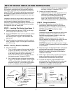
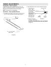
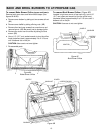
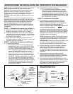
STEP 1 - Lo catin g The Bracket (see figure 1)
A. Determine where the right rear “EDGE” of the range
will be located and mark the floor or wall.
B. Place the BRACKET 15/16² (24 mm) from the marked
“EDGE” toward center of opening and against the
back wall as shown in figure 1, with orientation hole
against wall.
C. Use the bracket as a template and mark the required
holes, as shown in figure 1 for the type of construction
you will be using.
STEP 2 - Anti-Tip Bracket Installation
A. Wood Construction:
1. Floor: Locate the center of the two holes identified
in figure 1 as “HOLES FOR FLOOR”. Drill a 1/8²
(3 mm) pilot hole in the center of each hole (a nail
or awl may be used if a drill is not available).
Secure the ANTI-TIP bracket to the floor with the
two screws provided. Proceed to STEP 3.
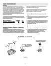
2. Wall: Locate the center of the two holes identified
in figure 1 as “HOLES FOR WALL. Drill an angled
1/8² (3 mm) pilot hole in the center of each hole
as shown in figure 2. (A nail or awl may be used if
a drill is not available). Secure the ANTI-TIP
bracket to the wall with the two screws provided
as shown in figure 2. Proceed to STEP 3.
B. Cement or Concrete Construction:
1. Suitable screws for concrete construction can be
obtained at a hardware store. Drill the required
size hole for the screws obtained into the
concrete at the center of the holes identified in
figure 1 as “HOLES FOR FLOOR”. Secure the
ANTI-TIP bracket to the floor. Proceed to STEP 3.
STEP 3 - Range Installatio n
A. For safety considerations as well as optimum
performance, adjust the range so it is level and to
desired height prior to installing in cabinet opening.
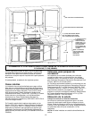
NOTE: Cooktop MUST
be flush or above
countertop.
Levelness may be checked by placing a spirit level or
a large pan of water on the cooktop or oven rack.
Adjust the range by tipping it forward or back and
rotate the leveling feet as required.
NOTE: A minimum clearance of 1/4² (6 mm) is
required between the range and the leveling foot that
will engage the anti-tip bracket, (see figure 2).
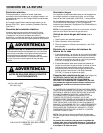
CAUTION: Damage to the range may occur if range
is moved or lifted by grasping the main top, backguard
or door handles.
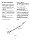
B. Align the range to its designated location and prepare
to slide it back into position. Connect gas line and
plug in power cord to outlet following guidelines
outlined in connecting the range and remainder of
installation instructions.
C. Slide range in place visually inspecting to verify that
power cord and gas line are freely routed and
contained within recessed area of back panel.
D. To check the range for proper installation of the
anti-tip bracket, use a flashlight and look underneath
the bottom of the range to see that the right rear
leveling foot is engaged in the bracket slot.
FIGURE 1
FIGURE 2
15/16² (24 MM) FROM
EDGE OF RANGE
LEVELING FOOT
ANTI-TIP BRACKET
ORIENTATION HOLE
HOLES FOR WALL
MARKED EDGE OF
RANGE
HOLES FOR FLOOR
(EACH SIDE)
ATTACH ANTI-TIP
BRACKET WITH
(2) LONG SCREWS
SCREWS MUST
ENTER WOOD
OR METAL
WALL PLA TE
ANTI-TIP
BRACKET
SCREW BRACKET
TO WALL
RANGE
BOTTOM
SLIDE IN TO SECURE
1/4²
(6 MM)
MIN.
NOTE: USE A MINIMUM OF (2) SCREWS
TO INSTALL ANTI-TIP BRACKET
TO THE WALL OR FLOOR.