


-5-
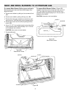
CONNECTING THE RANGE
Electric Supply
The appliance, when installed, must be electrically
grounded in accordance with local codes or, in the
absence of local codes, with the National Electrical Code,
ANSI/NFPA 70.
In Canada the range must be installed in accordance with
the current CSA Standard C22.1 - Canadian Electrical
Code Part 1.
Electrical Supply Connection
The range requires 120 volts, 60 cycle alternating current
from a grounded outlet with a 15 amp circuit breaker. See
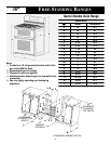
serial plate for rating, located on flip-up plate at the rear of
upper left hand corner of backguard.
Electrical Grounding Instructions
This appliance is equipped with a (three-prong)
grounding plug for your protection against shock
hazard and should be plugged directly into a properly
grounded receptacle. Do not cut or remove the
grounding prong from this plug.
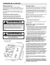
DISCONNECT ELECTRICAL SUPPLY
BEFORE SERVICING THE APPLIANCE.
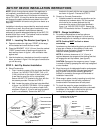
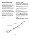
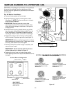
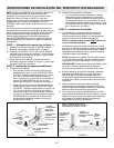
OVEN GAS SHUT-OFF VALVE
FIGURE 3
MANIFOLD
SHUT-OFF VALVE
Gas Supply
Installation of this range must conform with local codes or,
in the absence of local codes, with the National Fuel Gas
Code, ANSI Z223.1-latest edition.
In Canada the range must be installed in accordance with
the current CGA Standard CAN/CGA-B149 - Installation
Codes for Gas Burning Appliances and Equipment and/or
local codes.
NOTE: If oven burners do not ignite, check oven gas
shut-off valve position.
Oven Gas Shut-Off Valve (See figure 3)
1. Remove rear burner knob.
2. Remove spill guard.
3. Rotate to 9:00 position to turn on and 12:00 position to
turn off.
Checking Pressure Of Hou se Pipin g
System
1. The appliance and its individual shutoff valve must be
disconnected from the gas supply piping system during
any pressure testing of that system at test pressures in
excess of 1/2 lbs./sq. in. (3.5 kPa) (13.8 in. water
column).
2. The appliance must be isolated from the gas supply
piping system by closing its individual manual shutoff
valve during any pressure testing of the gas supply
piping system at test pressures equal to or less than
1/2 lbs./sq. in. (3.5 kPa) (13.8 in. water column).
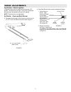
Gas Supply Connection (See figure 4)
A TRAINED SERVICEMAN OR GAS APPLIANCE
INSTALLER MUST MAKE THE GAS SUPPLY
CONNECTION. Leak testing of the appliance shall be
conducted by the installer according to the
instructions given in section h.
NATURAL GAS SUPPLY LINE MUST HAVE A NATURAL
GAS SERVICE REGULATOR. INLET PRESSURE TO
THIS APPLIANCE SHOULD BE REDUCED TO A
MAXIMUM OF 14 INCHES WATER COLUMN (0.5
POUNDS PER SQUARE INCH (P.S.I.) LIQUEFIED
PETROLEUM (L.P.)
/PROPANE GAS SUPPLY LINE
MUST HAVE A L.P. GAS PRESSURE REGULATOR.
INLET PRESSURE TO THIS APPLIANCE SHOULD BE
REDUCED TO A MAXIMUM OF 14 INCHES WATER
COLUMN (0.5 P.S.I.). INLET PRESSURES IN EXCESS
OF 0.5 P.S.I. CAN DAMAGE THE APPLIANCE
PRESSURE REGULATOR AND OTHER GAS
COMPONENTS IN THIS APPLIANCE AND CAN
RESULT IN A GAS LEAK.
NOTE: This range is shipped from the factory set for
Natural Gas at 5² water column pressure.
Gas supply pressure for testing regulator must be at
least 1²
²²
² water column pressure above manifold
pressure shown on serial plate.