


101
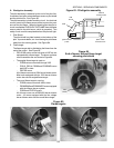
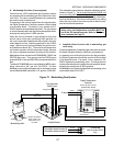
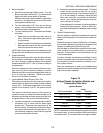
Figure 75
Voltage Checks for Ignition Module and
Combination Gas Valve
Ignition Module
Voltage
Test Points Marked Fused Nonfused
MV/PV to PV 3 VAC 24 VAC
MV/PV to MV 12 VAC 24 VAC
Combination Gas Valve
TR to TH 12 VAC 24 VAC
TH/TR to TR 3 VAC 24 VAC
NOTE: Information on the fused ignition module is provided
for reference only. All ovens produced 1988 or later use the
nonfused module. The fused module is no longer available.
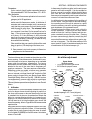
5. Burner Operation
a. Shut off the manual gas valve for oven. Turn the
Burner and Heat switches ON. The spark should
begin at the pilot burner within 30 seconds.
With the manual gas valve turned off, no gas will be
present; so, the spark will continue for the lockout
timing period of 90 seconds.
b. Turn the Heat switch OFF, then turn on the gas
supply. Set the temperature controller set point
above the actual oven temperature.
c. Turn the Heat switch ON. The system should start
as follows:
Spark turns on and pilot gas valve opens at
once. Pilot burner ignites after gas reaches
the pilot burner.
Spark cuts off when pilot flame is established.
Main gas valve opens and main burner lights
after gas reaches the burner ports.
NOTE: Main burner flame may not be satisfactory until
the gas input and combustion air have been adjusted.
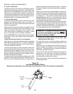
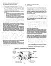
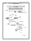
6. Check Grounding
Electrical ground connections must be clean and tight.
If the lead wire is damaged or deteriorated, use only
No. 14 to 18 gauge, moisture-resistant thermoplastic
insulated wire with a 221°F (105°C) minimum rating as
a replacement.
Excessive temperature at the ceramic flame rod insu-
lator can also permit electrical leakage to ground.
Examine the flame rod and mounting bracket, and cor-
rect if it is bent out of position. Replace the ignitor/
sensor if the insulator is cracked.
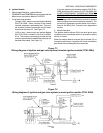
7. Ignition Module Flame Sensor Circuit Test
The ignition module provides AC power to the ignitor/
sensor which the pilot burner flame rectifies to direct
current (DC). If the flame signal back to the control
module is not at least 2.0 mA DC, the system will lock
out.
The output of the flame sensing circuit cannot be
checked directly, so check the flame sensing circuit
indirectly by checking the flame sensing current form
the ignitor/sensor to the control module as follows.
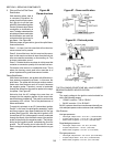
a. Connect a ampmeter or multimeter set to read DC
microamps (mA) in series with the flame signal
ground wire. Disconnect the ground wire at the
control module. Connect the red (positive) lead of
the meter to the free end of the ground wire. Con-
nect the black (negative) meter lead to the ground
terminal on the ignition module.
b. Restart the system and read the meter. The flame
sensor current must be at least 2.0 mA, and the
reading must be steady. If the reading is below 2.0
mA or if the reading is unsteady, check the pilot
flame and electrical connections as described
above. Also, replace the ignitor/sensor if the ce-
ramic insulator is cracked.
If the reading still is unsteady, it may be necessary
to adjust the pilot pressure. Refer to Pilot Pres-
sure under Servicing the Combination Valve on Page
98.
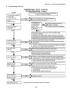
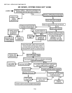
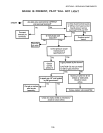
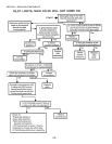
8. System Troubleshooting.
Start the system by setting the temperature controller
above room temperature, and observe the system re-
sponse.
Establish the type of system malfunction or deviation
from normal operation by using the Intermittent Pilot
System Troubleshooting Table on Page 103.
Use the table by following the questions in the boxes.
If the condition is true (answers yes), go down to the
next box. If the condition is not true (answers no), go
to the box alongside.
Continue checking and answering conditions in each
box until a problem and/or the repair is explained. Use
the Component Checks section as necessary to per-
form system checks.
After any maintenance or repair, the troubleshooting
sequence should be repeated until the procedure ends
with normal system operation.
SECTION 3 - SERVICING COMPONENTS