


142
SECTION 3 - SERVICING COMPONENTS
B. PS310/360-series ovens
1. Description of heating system
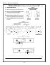
All PS310/360-series electric ovens use an on-off sys-
tem for heater activation. When the oven demands
heat, the temperature controller activates mercury
contactors that in turn activate the heaters at 100%
power. The contactors open when the temperature rises
to 2 degrees above the set point, and close when the
ovens temperature falls 2 degrees Fahrenheit below
the set point. Because of residual heat within the oven,
however, the temperature swing after preheating is about
5 degrees Fahrenheit above and below the set point.
IMPORTANT: Because the PS310/360-series
electric oven uses an on-off system for heater
activation, the temperature controller
MUST
be set to the on-off operating mode. Refer to
Temperature Controller on Page 30.
Each bank of heaters (3 total) uses one mercury
contactor and three fuses. 30A fuses were used
through 1/91. Heat inside the machinery compartment
can de-rate these fuses, causing the fuse to blow pre-
maturely. To correct this situation, 40A fuses were used
2/91 and later.
NOTE: All control wire used on this oven is AWM rated
at 221°F/105°C. DO NOT replace with lower rated wire.
2. Part number reference
Part No. Description
27374-0001 Heating element, 208V
27374-0002 Heating element, 240V
27374-0003 Heating element, 380V
28041-0016 Mercury contactor, 3 pole, 30A
27170-0251 Contactor tube replacement kit
27170-0250 Coil replacement kit
28154-0002 Fuse, 30A, class M (early)
28150-0134 Fuse, 40A, class T (current)
27021-0016 Fuse block, 40A (used when upgrading
from 30A to 40A fuse - qty. 3 reqd.)
3. Supply
Ovens have a 208V, 220-240V, 380V, 416V or 480VAC
electrical supply. The control current of the oven oper-
ates at 110V, single phase. If the oven was specified
for a 3 wire system, it was supplied with an optional
control transformer to step the 3 phase current down
for the control circuit. If the oven was specified for a 4
wire system, the 4th (neutral) wire is utilized to split 2
of the 3 incoming 3 phase legs and obtain a separate
110V circuit.
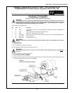
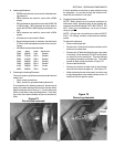
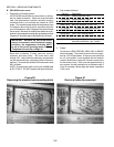
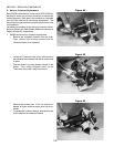
Figure 80
Removing the element bank mounting bolts
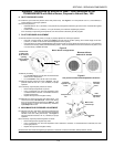
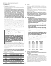
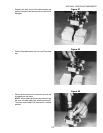
Figure 81
Electrical leads disconnected