


18
SECTION 3
OPERATION
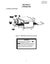
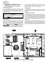
II. COMPONENT INFORMATION AND
LOCATION (Figures 3-1 and 3-2)
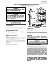
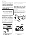
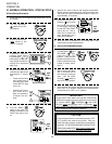
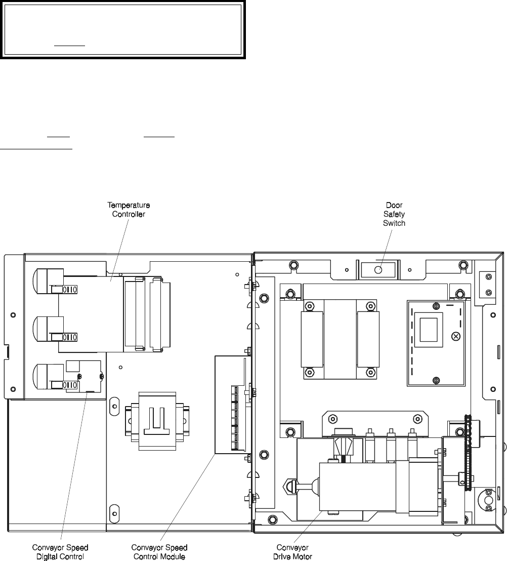
A. Door Safety Switch
The Door Safety Switch is located at the lower right side
of control panel opening. Opening the control panel door
permits this switch to open, disconnecting power to all
electrical controls.
CAUTION
Do NOT touch the wires going to this safety switch.
Current is always present.
B. Blower Switch
The blower switch has two positions. The switch must
be “ON” or “I” for the main blowers to come on and permit
the oven to run. The fan circulates the air throughout the
oven and
must stay on during baking and during the
cool down cycle above 200°F (93°C) to prevent blower
bearing damage. To protect the blower motor and
bearings a thermostatic override is built into the oven.
If the temperature inside the oven is over 180°F (82°C)
the main blower will continue to run after the blower
switch is turned to the “OFF” or “O” position.
C. Heat Switch
The “Heat Switch” allows the burner to activate. Activation
is determined by the settings on the Digital Temperature
Controller.
D. Temperature Controller
The temperature controller is a solid-state, PID type to
maintain the operator-set temperature. The temperature
controller continuously monitors the oven temperature and
turns on the modulating solid state relay controller. The
heat is on for the time required to maintain a constant oven
temperature.
The temperature controller contains a low-limit switch
which allows the oven to cool down to 200°F (93°C) before
shutting off the blower. A high-limit indication (ALM 1) will
appear on the display if the oven reaches 650°F (343°C).
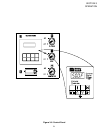
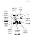
Figure 3-2. Interior View of Control Console