


2
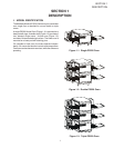
SECTION 1
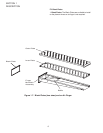
DESCRIPTION
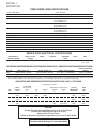
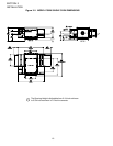
PS520 SERIES OVEN SPECIFICATIONS
Conveyor Belt Width 18.00″ (457mm)
Heating Zone Length 20.00″ (5098mm)
Baking Area Square Feet 2.5 sq. ft. (0.23 sq. m.)
Overall Dimension – Standard Single Oven w/Legs 42.00″ (1067mm) L ×
35.21″ (894mm) W ×
21.10″ (536mm) H ×
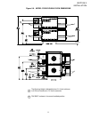
Overall Dimension – Double Oven 42.00″ (1067mm) L ×
35.21″ (894mm) W ×
36.64″ (931mm) H x
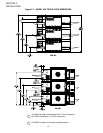
Overall Dimension – Triple Oven 42.00″ (1067mm) L x
35.21″ (894mm) W ×
48.19″ (1224mm) H ×
Weight of Single Oven 250 lb (93.3kg)
Shipping Weight 325 lb (121.3kg)
Shipping Cube 22.1 ft
3
(0.62 m
3
)
Operating Range 8.3 kW/hr
BTU's – Natural or Propane Gas 40,000 BTU/HR
Gas Input – Natural or Propane Gas 1/2″ NPT
Maximum Operating Temperature 600°F (316°C)
Warm-up Time 20 min.
Belt Speed Limits 1-10 minutes
SERIES PS520 ELECTRICAL SPECIFICATIONS
Main Blower & Control Circuit Phase Frequency Amperage Poles Wires
Elements Voltage Voltage Draw
208-240V 208-240V 1 Ph 50/60 Hz 1.5 Amp 2 Pole 3 Wire
(2 hot, 1 grd)
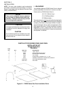
GAS ORIFICE AND PRESSURE SPECIFICATIONS (PER OVEN CAVITY) - CE OVENS
Supply (Inlet) Pressure
IT,PT,ES,SE,
Main UK,CH,IT,AT, SE,CH,AT,DK, BE,IE,IT,PT, Orifice Rated
Gas Orifice DK,FI DE BE,FR FI,DE,NL ES,UK (Manifold) Heat
Type dia.
I
2H
I
2E
I
2E+
I
3B/P
I
3+
Pressure Input
G20 2.3749 20 20 20 -- -- 11.21 22.36
mm mbar mbar mbar mbar kW-hr.
G25 2.3749 -- -- -- -- -- 16.19 22.36
mm mbar kW-hr.
G30 1.3970 -- -- -- 29 or 50 28-30, 37 26.2 22.59
mm mbar or 50 mbar mbar kW-hr.
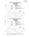
GAS ORIFICE AND PRESSURE SPECIFICATIONS (PER OVEN CAVITY) - DOMESTIC AND STANDARD EXPORT OVENS
Orifice (Manifold)
Gas Type Main Orifice I.D. Bypass Orifice I.D. Supply (Inlet) Pressure Pressure
Natural 0.082” (2.08mm, #45 drill) 0.073” (2.0574mm, #49 drill) 6-12” W.C. (14.9-29.9mbar) * 3.5” W.C. (8.72mbar)
Propane 0.057” (1.45mm, #46 drill) 0.052” (1.85mm, #55 drill) 11-14” W.C. (27.4-34.9mbar) * 7” W.C. (17.44mbar)
*
The gas supply pressures and orifice sizes shown are for ovens installed in North America. The required gas supply pressures and orifice
sizes of ovens installed in other locations are dependent on the local gas type and on all applicable local codes.
NOTE
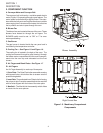
Wiring Diagrams are contained in Section 6 of this Manual
and are also located inside the oven at the
bottom of the Control Panel.
Additional electrical information is provided on the oven's serial plate.
This Manual Must Be Kept For Future Reference.