


18
B. Connection
Check the oven’s gas supply requirements before making the
gas utility connection. Gas supply requirement are listed on the
oven’s serial plate and in Table 1-4. Gas Orifice and Pressure
Specifications (in Section 1, Description).
Check the serial plate to determine the type of gas (Propane or
Natural) to be used with the oven.
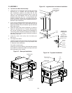
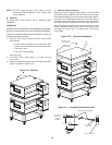
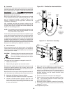
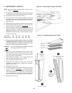
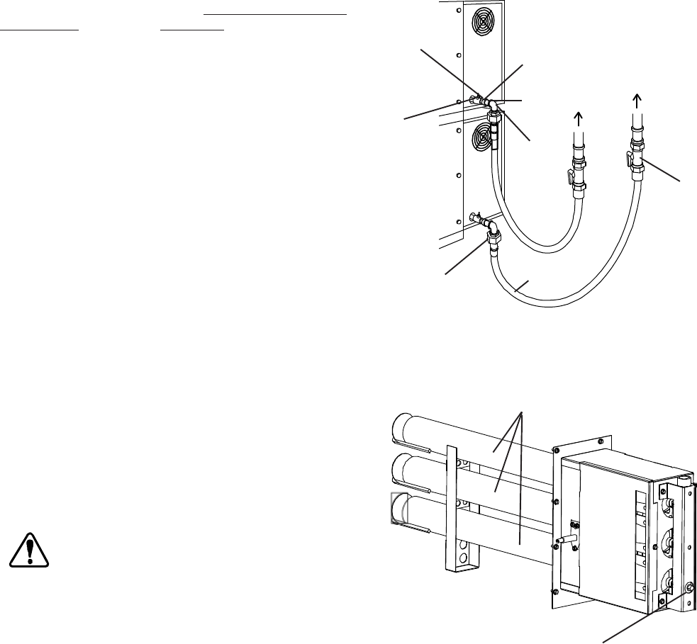
Refer to the instructions in the gas hose package (included
in the Installation Kit) before connecting the gas line. One
gas line connection method is shown in Figure 2-18;
however, compliance with the applicable standards and
regulations is mandatory.
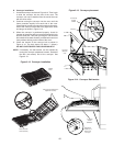
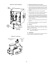
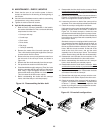
Inlet, regulated, and pilot gas pressure readings can be
taken using a digital tube manometer at the tap location shown
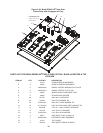
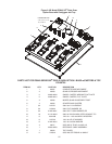
in Figure 2-19. Figure 2-19 shows the burner assembly and
Figure 2-21 shows the gas valve.
NOTE:
The installation must conform with local codes or in the
absence of local codes, with the National Fuel Gas
Code, ANSI Z223.1-latest edition.
Certain safety code requirements exist for the installation of gas
ovens; refer to the beginning of Section 2 for a list of the installation
standards. In addition, because the oven is equipped with cast-
ers, the gas line connection shall be made with a connector that
complies with the Standard for Connectors for Movable Gas
Appliances, ANSI Z21.69 (in U.S.A.), as well as a quick-discon-
nect device that complies with the Standard for Quick-Disconnect
Devices for Use With Gas Fuel, ANSI Z21.41 (in U.S.A.).
C. Gas Conversion
Where permitted by local and national codes, it is possible to
convert ovens from natural to propane gas, or from propane to
natural gas. Use the appropriate Middleby Gas Conversion Kit
for the specific oven model.
CAUTION: The terms of the oven’s warranty require all start-
ups, conversions and service work to be per-
formed by a Middleby Authorized Service Agent.
D. PS840 Propane Conversion
Two items have to be changed, to change the oven to LP:
1. Replace main orifices.
2. Adjust main gas regulator per instructions below.
Disconnect the manifold union closest to the main burner, and
remove the manifold assembly (four screws). Slide out the
manifold assembly (leaving the ignition and sense wires con-
nected). Replace the main orifices.
Replace the main orifices on the manifold assemblies with the LP
units, and replace the manifold assembly. Reconnect the union.
E. Adjusting the Maximum Pressure Setting
1. Disconnect pressure feedback connection (if appcable).
2. Connect a suitable pressure gauge to pipe line or to
outlet pressure tap of gas control concerned, to mea-
sure burner pressure (measuring point must be as near
to burner as possible).
Figure 2-19. Gas Burner Assembly
Figure 2-18. Flexible Gas Hose Installation
Gas Burner
Manifold Pressure Tap
To Gas
Supply
Pipe
90°
Elbow
Quick-
disconnect
device
Flexible
Gas Hose
Full-Flow
Gas
Shutoff
Valve
3/4″ gas
pipe nipple
3/4″-1/2″
gas pipe
reducer
Individual gas
connection for
each oven
cavity
1/2″ gas
pipe nipple
1/2″ gas line
tee with
pressure tap
3. Make sure that the appliance is in operation and the
Moduplus
®
coil is energized with maximum current.
4. If maximum rate pressure needs adjustment, use an 8 mm
wrench to turn adjustment screw for maximum pressure
setting (clockwise to increase or counter-clockwise to
decrease pressure), until the desired maximum outlet
pressure is obtained.
5. Disconnect electrical connection of the Moduplus
®
.
6. Check minimum pressure setting and readjust if neces-
sary. (See Adjusting Minimum Pressure Setting for
proper adjusting procedure.)
7. Reconnect pressure feedback connection (if appcable).
8. If minimum and maximum pressures are set, wire the
Moduplus
®
in circuit.
9. Close pressure tap screw.