


2
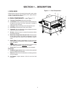
I. OVEN SPECIFICATIONS
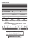
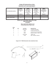
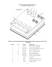
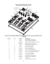
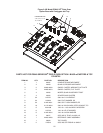
Table 1-1 Dimensions
Single Oven Double Oven Triple Ove
Overall Height 48-3/16″ (1219mm) 62-3/4″ (1575mm) 78-11/16″ (1981mm)
Overall Depth 60″ (1524mm) 60″ (1524mm) 60″ (1524mm)
Overall Length 76-1/2″ (1930mm) 76-1/2″ (1930mm) 76-1/2″ (1930mm)
Conveyor Width – belt width is 32″ 33-1/2″ (838mm) 33-1/2″ (838mm) 33-1/2″ (838mm)
or 2 × 15″ (381mm) or 2 × 15″ (381mm) or 2 × 15″ (381mm)
Shortened Exit Conveyor - 24
″″
″″
″
Single Oven Double Oven Triple Ove
Overall Depth 52.75″ (1340mm) 52.75″ (1340mm) 52.75″ (1340mm)
Overall Length 69″ (1753mm) 69″ (1753mm) 69″ (1753mm)
* All other dimension are the same
Recommended Minimum Clearances
Rear of Oven to Wall 3″ (76mm) 3″ (76mm) 3″ (76mm)
Control end of conveyor to Wall 1″ (25.4mm) 1″ (25.4mm) 1″ (25.4mm)
Non-control end of conveyor to Wall) 1″ (25.4mm) 1″ (25.4mm) 1″ (25.4mm)
Table 1-2: General Specifications PS840 GAS 32
″″
″″
″ Belt 24
″″
″″
″ Belt
Weight 1150 lbs. (522kg) 1150 lbs. (522kg)
Rated Heat Input 99,000 BTU (25,000kcal, 29 kW/hr) 99,000 BTU (25,000kcal, 29 kW/hr)
Maximum Operation Temperature 600°F / 315°C 600°F / 315°C
Air Blowers Two Blowers at 1900 RPM Two Blowers at 1900 RPM
Warmup Time 15 min. 15 min.
Table 1-3: Electrical specifications for PS840G gas ovens
Main Blower Control Circuit Phase Freq Current Poles Wires
Voltage Voltage Draw
208-240VAC 208-240VAC 1Ph 50/60Hz 11-9.6 Amp 2 Pole 3 Wire (2 hot, 1 gd)
Table 1-4: Gas orifice and pressure specifications for PS840G gas ovens
Gas Main Orifice I.D. Supply (Inlet) Orifice (Manifold) Bypass
Type PS840G Pressure Pressure Pressure
Natural 0.1065″ (0.120mm) 6-8″ W.C. (14.9 - 19.9mbar) 3.5″ W.C. (8.7mbar) 0.25-0.3″ W.C. (0.6-0.8 mbar)
Propane 0.067″ (1.9mm) 11-14″ W.C. (27.4 - 34.9mbar) 10.0″ W.C. (24.9mbar) 0.9-1.0″ W.C. (2.2-2.5 mbar)
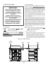
IMPORTANT –
Additional electrical information is provided on the oven’s serial plate, and on the wiring diagram inside the
machinery compartment.
NOTE
Wiring Diagrams are contained in Section 5 of this Manual
and are also located inside the oven at the
bottom of the Control Panel.
Additional electrical information is provided on the oven's serial plate.
This Manual Must Be Kept For Future Reference
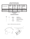
GAS ORIFICE AND PRESSURE SPECIFICATIONS (PER OVEN CAVITY) - CE OVENS
Supply (Inlet) Pressure
IT,PT,ES,SE,
Main UK,CH,IT,AT, SE,CH,AT,DK, BE,IE,IT,PT, Orifice Rated
Gas Orifice DK,FI NL DE BE,FR FI,DE,NL ES,UK (Manifold) Heat
Type dia.
I
2H
I
2L
I
2E
I
2E+
I
3B/P
I
3+
Pressure Input
G20 0.120″ 20 -- 20 20 -- -- 11.21 22.36
(3.05 mm) mbar mbar mbar mbar kW-hr.
G25 0.120″ -- 25 -- -- -- -- 16.19 22.36
(3.05 mm) mbar mbar kW-hr.
G30 0.075″ -- -- -- -- 29 or 50 28-30, 37 26.2 22.59
(1.9 mm) mbar or 50 mbar mbar kW-hr.