


iv
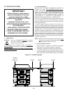
NOTE
Wiring Diagrams are in Section 5 of this Manual.
The diagram for each oven is also on the lower
inner surface of its Control Console.
Page
SECTION 1 – DESCRIPTION ............................................ 1
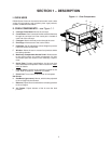
I. OVEN USES ............................................................ 1
II. OVEN COMPONENTS ............................................ 1
A. Conveyor Motor Drive ................................... 1
B. Crumb Pans .................................................. 1
C. Conveyor ....................................................... 1
D. End Plugs ...................................................... 1
E. Eyebrows ...................................................... 1
F. Window ......................................................... 1
G. Machinery Compartment Access Panel ........ 1
H. Serial Plate .................................................... 1
I. Control Panel ................................................ 1
J. Photo Cell ..................................................... 1
K. Gas Burner .................................................... 1
L. Blowers ......................................................... 1
M. Air Fingers ..................................................... 1
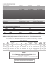
III. OVEN SPECIFICATIONS ........................................ 2
A. Dimensions ................................................... 2
B. General Specifications .................................. 2
C. Electrical Specifications for
PS840 Gas Ovens ........................................ 2
D. Gas Orifice and Pressure Specifications
for PS840 Gas Ovens ................................... 2
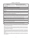
SECTION 2 – INSTALLATION ........................................... 3
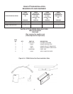
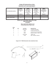
I. BASE PAD KIT ......................................................... 4
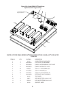
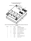
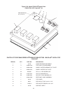
II. INSTALLATION KIT ................................................. 6
III. VENTILATION SYSTEM ........................................ 12
A. Requirements .............................................. 12
B. Recommendations ...................................... 12
C. Other Ventilation Concerns ......................... 12
IV. ASSEMBLY ............................................................ 13
A. Base Pad, Legs, Casters ............................ 13
B. Stacking ....................................................... 14
C. Restraint Cable Installation ......................... 14
D. Conveyor Installation .................................. 15
E. Standoff Installation .................................... 15
V. FINAL ASSEMBLY ................................................. 16
VI. ELECTRICAL SUPPLY .......................................... 16
Connection ....................................................... 17
VII. GAS SUPPLY ........................................................ 17
A. Gas Utility Rough-In Recommendations ..... 17
B. Connection .................................................. 18
C. Gas Conversion .......................................... 18
D. Propane Conversion ................................... 18
E. Adjusting the Maximum Pressure Setting ... 18
F. Adjusting the Minimum Pressure Setting .... 19
G. Checkout ..................................................... 19
H. Maintenance ............................................... 19
Page
SECTION 3 – OPERATION .............................................. 20
I. LOCATION AND DESCRIPTION OF CONTROLS 20
II. NORMAL OPERATION, STEP-BY-STEP ................ 21
A. Main Screen ................................................ 21
B. Daily Startup Procedure .............................. 21
C. Daily Shutdown Procedure ......................... 21
III. QUICK REFERENCE: TROUBLESHOOTING ...... 22
IV. SCREEN ALERTS ................................................. 22
SECTION 4 – MAINTENANCE ........................................ 23
I. MAINTENANCE – DAILY ....................................... 23
II. MAINTENANCE – MONTHLY ............................... 24
III. MAINTENANCE – EVERY 3 MONTHS ................. 25
IV. MAINTENANCE – EVERY 6 MONTHS ................ 26
V. KEY SPARE PARTS KIT ....................................... 27
SECTION 5 – ELECTRICAL WIRING DIAGRAM ............ 28
I. WIRING DIAGRAM, 840 GAS OVEN, 208/240V,
50/60 Hz, 1 Ph ....................................................... 28
TABLE OF CONTENTS