


ERV-17LGH-F-RX3-E (Feb. 2009)
Lossnay ERV
LGH-F-RX3-E
Performance Certied
to ARI 1060 Standard
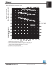
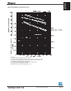
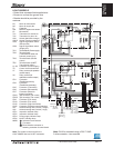
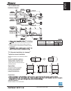
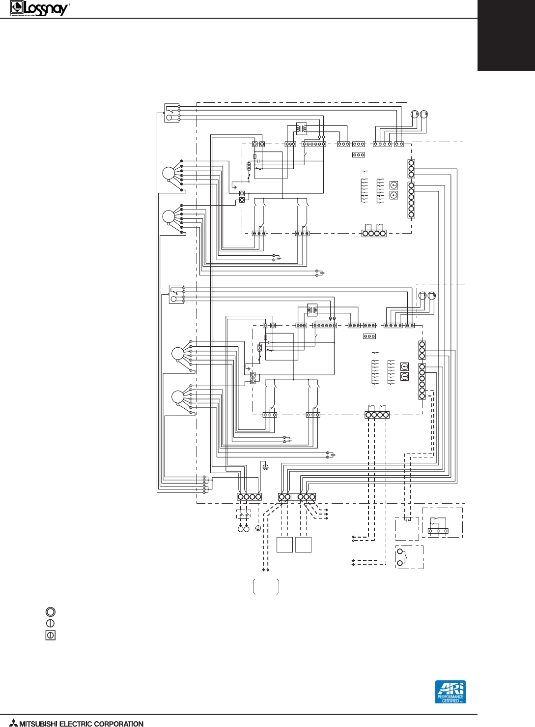
LGH-F1200RX3-E
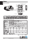
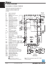
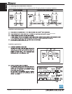
• Dotted lines represent eld-supplied wire.
• Be sure to connect the ground wire.
• Breaker should be provided by the
customer.
01
01
)UE ni dilavnI(
ZH06 ~ V022
ZH05 ~ V042 - 022
YLPPUS REWOP
NL
EP5NL
S6
B
A
Am001 V5 CD A2 V42 CD
Am001 V022CA A2 V042CA
N.IMX.AM
tuptuo rotinom noitarepO
Am001 V5 CD A1 V42 CD
Am001 V022CA A1 V042CA
N.IMX.AM
tuptuo rotinom noitcnuflaM
M
2
M
1
78
9
31
S
B
A
6
5
4
1
3
2
2
3
1
4
5
6
A
B
S
9
78
M
2
M
1
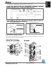
)noitanidrobuS(
)niaM(
elbac noiissimsnarT
tinu yanssoL
stinu 7 x.aM
5BT2MT1MT
elbac noiissimsnart-TEN-M
eriw dleihS
C
C
)AR( 2HT
)AO( 1HT
)AO( 1HT
)
AR( 2HT
-ZP
E-FS25
-ZP
E-BLS14
5NC
SL
tcatnoc-a
RT
C
C
ZNR101
A3.6V052
ESUF
C101
DSA1
ZNR102
BROWN
2-8NC
RED
1-8NC
5
1
5
1
4WS
HIGH
EXTRA
× 3
× 4
× 1
BLACK
GREY
YELLOW
WOLLEY/NEERG
ORANGE
WHITE
ROTOM NAF
YLPPUS
HIGH
9NC
01NC
ROTOM NAF
TSUAHXE
BLUE
HIGH
EXTRA
HIGH
× 5
× 2
3WS
× 8
× 7
3MT
tupni lortnoc lanretxE
3
tcatnoc-a
2MT
)ralopnon(
CD V42
milS .rM
ro V21
degrahcnU
5BT
23NC
2S
1S
1
1
6
1NC
6NC2NC
7NC
rotcennoc tceles woL/hgiH
dergahcnU
woL
hgiH
61NC
MG
61NC
YELLOW
RED
BROWN
BROWN
ORANGE
ORANGE
GREY
GREY
BLUE
BLUE
NWORB
EULB
NWORB
EULB
WHITE
WHITE
1WS
5WS2WS
2AS
1AS
1AS
2AS
5WS
2WS
1WS
WHITE
WHITE
BLUE
BLUE
GREY
GREY
ORANGE
ORANGE
BROWN
BROWN
RED
YELLOW
)61NC(
MG
7NC
2NC
6NC
1NC
6
1
1
1S
2S
)23NC(
)5BT(
)2MT(
3
)3MT(
× 7
× 8
3WS
× 2
× 5
HIGH
EXTRA
HIGH
BLUE
TSUAHXE
ROTOM NAF
01NC
9NC
HIGH
YLPPUS
ROTOM NAF
WHITE
ORANGE
YELLOW
GREY
BLACK
× 1
× 4
× 3
EXTRA
HIGH
4WS
1
5
1
5
1-8NC
RED
2-8NC
BROWN
ZNR102
DSA1
C101
ESUF
A3.6V052
ZNR101
C
RT
SL
5NC
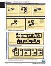
M1 Motor for exhaust fan
M2 Motor for supply fan
C Capacitor
GM Motor for bypass movement
LS Microswitch
TH1 Thermistor for outside air
TH2 Thermistor for return air
SW1 Switch (Main/Sub change)
SW2,5 Switch (Function selection)
SW3 High/X-High select switch
(Exhaust fan)
SW4 High/X-High select switch
(Supply fan)
TM1 Terminal block (Power supply)
TM2 Terminal block
(Transmission cable and
external control input)
TM3 Terminal block (Monitor
output)
TB5 Terminal block (M-NET
Transmission cable)
S1, S2 Connector (Power supply)
TR Control circuit transformer
X7 Relay contact (for operation
monitor output)
X8 Relay contact (for
malfunction monitor output)
CN1 Connector
(Transformer primary)
CN2 Connector
(Transformer secondary)
CN5 Connector (Thermistor)
CN6 Connector (Microswitch)
CN7 Connector (Motor for
bypass operation)
CN8-1 Tab connector (Fan motor)
CN8-2 Tab connector (Fan motor)
CN9 Connector (Fan motor)
CN10 Connector (Fan motor)
CN16 Connector (High/Low switch)
CN32 Connector (Remote control selection)
SA1 Address setting rotary switch (10 digit)
SA2 Address setting rotary switch (1 digit)
LED1 Inspection indicator lamp
LED2 Inspection indicator lamp
LED4 Power supply indicator lamp
LED6 M-NET indicator lamp
MARK: Indicates Terminal block
Connector
Board insertion connector or
fastening connector of control board
Note: The double control board for the
LGH-F12000RX has two M-NET addresses.
Note: CN16 is accessed using a PAC-715AD
3-wire connector―two required.