


suppl
y
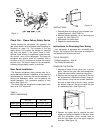
connects to the terminal block at the rear of
the refri
g
erator
(
See Fi
g
ure 9 on pa
g
e 8
)
. The 12 volt
DC should enter the refri
g
erator’s enclosure near the
refri
g
erator’s terminal block. The 12 volt DC connects
at
(
2
)
one
q
uarter inch
q
uick connects. The positive
DC input lead connects to terminal marked
(
+
)
, and
the DC
g
round input lead connects to terminal
marked
(
-
)
.
CAUTION: Correct polarity must be ob-
served when connecting the DC supply.
Do not use the chassis of the refrigerator
or the vehicle frame as one of the conduc-
tors. Connect DC supply wires at the bat-
tery and route to the refrigerator.
The distance the current travels from the batter
y
to
the refri
g
erator dictates the wire size. Undersized
wire can result in a volta
g
e drop, which will affect the
watta
g
e output of the DC heater and result in re-
duced refri
g
erator performance. Norcold recommends
the installation of a fuse in the suppl
y
wirin
g
between
the batter
y
and the refri
g
erator. For optimum protec-
tion, install the fuse as close to the batter
y
as possi-
ble.
WARNING: A circuit overload can result in
an electrical fire when undersized wires or
improperly sized fuses are used. To pre-
vent a possible electrical fire, follow
R.V.I.A. A119.2 Standards, Norcold’s wire
size and fuse specifications, or applicable
state and local codes.
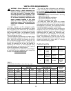
TABLE 3
12 VOLT SUPPLY WIRING AND FUSE SIZE
482, 462
452, 442
483, 463 453, 443
min.
wire
size
max.
fuse
size
min.
wire
size
max.
fuse
size
Min.
wire
size
max.
fuse
size
0 - 20’ 18
AWG
6 Amp 10
AWG
30
Amp
12
AWG
20
Amp
over
20’
18
AWG
6 Amp 8
AWG
40
Amp
10
AWG
30
Amp
If a wire size is installed which is lar
g
er than the
minimum size indicated the table above, it must be
fused in accordance with the R.V.I.A. A119.2 stand-
ard or local
g
overnin
g
codes.
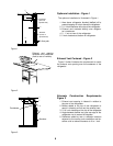
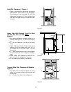
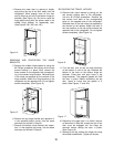
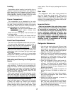
Chassis Bonding Connection
A No. 8 AWG copper conductor is commonl
y
used
to meet the chassis bondin
g
re
q
uirements of the Na-
tional Electric Code
(
ANSI/NFPA No. 70, Art. 551
)
.
When this conductor is used to bond the non-current
carr
y
in
g
metal parts of the refri
g
erator, a No. 10-32
bondin
g
terminal is provided to make the connection.
(
See Fi
g
ure 10
)
.
Hypot Test
A Dielectric Stren
g
th test
(
h
y
pot
)
has been con-
ducted at the factor
y
; this refri
g
erator does not re-
q
uire an additional test. If h
y
pot tests are conducted
on the vehicle’s 12 volt circuit, the 12 volts
must
be
disconnected from the refri
g
erator to protect the
flame i
g
nition circuit.
Testing the Vehicle’s Gas Supply Piping
When installation of the refri
g
erator is complete, the
propane
g
as suppl
y
pipin
g
must be inspected and
tested for leaks from the refri
g
erator to the main
g
as
suppl
y
tank. Use a leak detection solution.
Do not
test for leaks with an open flame.
If compressed air is used for leak testin
g
, the
g
au
g
e
pressure must not exceed 1/2 pound per s
q
uare inch
(
14 inches water column
)
.
The appliance and its individual shut-off valve
(
Fi
g
-
ure 11 on pa
g
e 10
)
must be disconnected from the
g
as suppl
y
s
y
stem durin
g
an
y
pressure testin
g
of that
s
y
stem at test pressures
g
reater than 1/2 psi
g
(
14
inches water column
)
.
The appliance must be isolated from the
g
as suppl
y
s
y
stem b
y
closin
g
its individual manual shut-off valve
(
Fi
g
ure 11 on pa
g
e 10
)
durin
g
an
y
pressure testin
g
of that s
y
stem at test pressure e
q
ual to or less than
1/2 psi
g
(
14 inches water column
)
.
Check the
g
as pressure to the refri
g
erator without
other
g
as appliances operatin
g
. The pressure should
not exceed 11 inches water column. With other appli-
ances operatin
g
the pressure should not be less than
10.5 inches water column.
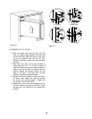
Fi
g
ure 10
10