


INSTALLATION INSTRUCTIONS
Certification and Code Requirements
The refri
g
erators described herein are certified un-
der the latest edition of ANSI Z21.19 Standards b
y
the American Gas Association
(
A.G.A.
)
for installa-
tion in mobile home or recreational vehicle and ap-
proval b
y
the Canadian Gas Association
(
CGA
)
.
Installation must be made in accordance with these
standards and with the installation instructions pro-
vided in this manual for the Norcold factor
y
warrant
y
to be in effect.
Installation must conform with local codes, or in the
absence of local codes, with the followin
g
standards
as applicable:
In the United States:
a. National Fuel Gas Code, ANSI Z223.1.
b. Manufactured Home Construction and Safet
y
Standard, Title 24 CFR, Part 23-80.
c. Standard for Recreational Vehicles,ANSI
A119.2, latest edition.
When an external electrical ener
gy
is utilized, the
refri
g
erator must be electricall
y
g
rounded in accord-
ance with local codes, or in the absence of local
codes, the National electrical Code, ANSI/NFPA 70.
In Canada:
a. Current CGA B149.1 and B149.2 installation
code for Propane Appliances and E
q
uipment..
b. Current CSA Z240.4.2 installation code for Pro-
pane Appliances and E
q
uipment in Recrea-
tional Vehicles.
c. Current CSA Z240.6.2/C22.2 No. 148 Electrical
Re
q
uirement for Recreational Vehicles.
When installed, the appliance must be electricall
y
g
rounded in accordance with the current Canadian
Electrical Code C22.2 Parts 1 and 2.
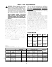
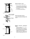
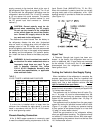
Cut-Out Dimensions
The refri
g
erators certified for built installation and
re
q
uires cut-out dimensions as indicated in Table 2
below.
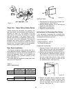
Combustion Seals
Combustion seals
(
foam strips
)
are attached to the
back surface of the refri
g
erator’s mountin
g
flan
g
es.
These seals isolate the products of combustion from
the vehicle’s livin
g
space.
The seals must be con-
tinuous between the wall and the mounting
flanges to
assure a complete combustion sea
l.
When installin
g
or removin
g
the refri
g
erator, insure
that the seals are not missin
g
or dama
g
ed.
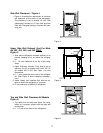
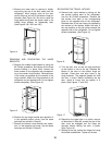
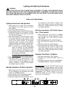
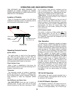
Lower Flange Installation
The lower mountin
g
flan
g
e and mountin
g
screws
are located in a clear plastic ba
g
positioned in the
coils at the rear of the refri
g
erator. After removin
g
the
plastic ba
g
, slide the refri
g
erator partiall
y
into the en-
closure and attach the lower mountin
g
flan
g
e. Install
the lower mountin
g
flan
g
e b
y
maneuverin
g
it under
the bottom control cover and secure with the screws
provided. Refer to Fi
g
ure 7.
Do not omit installa-
tion of the lower mounting flange. This flange is
part of the combustion seal.
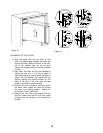
Securing the Refrigerator
Secure the refri
g
erator with screws throu
g
h the
mountin
g
flan
g
e holes at the front of the refri
g
erator
and the holes at floor level at the rear of the refri
g
-
erator. Screw covers are provided to cover the front
mountin
g
flan
g
e holes.
TABLE 2
REFRIGERATOR CUT-OUT OPENINGS
(
INCHES
)
Model
462, 463
482, 483
452,453
442,443
Hei
g
ht
52 7/8
59 7/8
43 1/4
30 7/8
Width
23 1/2
23 1/2
23 1/2
23 1/2
Depth
24
24
24
24
Fi
g
ure 7
8