


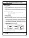
D. SERVICING THE MECHANICAL FLOATS
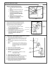
Resetting the Safety Float
1. Remove cover from cabinet.
2. Press down on the safety float
re-set button (see figure 8).
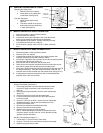
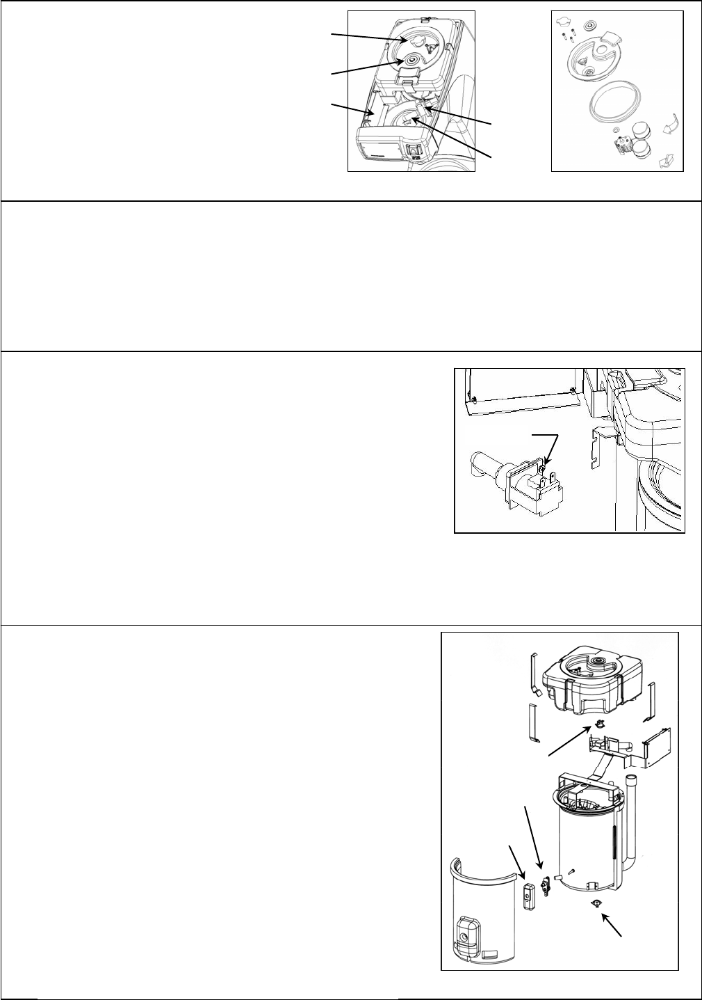
Float arm inspection
1. Remove float cap from top
reservoir.
2. Float arms should move up and
down freely and should not bind
or catch (see figure 9).
E. INSPECT AND REPLACE CIRCUIT BOARD FUSE
1. Disconnect power cord from electrical outlet.
2. Remove cover from cabinet.
3. Locate fuse at the lower right side of the circuit board (see
figure 8) and inspect the fuse filament for breakage.
4. If fuse appears to have blown, carefully remove it from the
circuit board and check it for continuity.
5. If fuse is blown, replace it with a 25 volt, 5 AMP, slow blow
fuse.
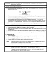
F. INSPECT AND REPLACE DUMP SOLENOID VALVE
1. Disconnect power cord from electrical outlet.
2. Remove cover from cabinet.
3. Locate dump solenoid (see figure 8) and visually inspect clear
solenoid valve body for mineral build up or debris.
4. If build up or obstruction has occurred, remove the hot tank assembly
from the outer cabinet (see section C).
5. Remove both sets of wires from the solenoid valve.
6. Remove from the solenoid valve both the silicone tube from the hot
tank and the angled silicone tube going to the spray head.
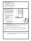
7. Remove the dump solenoid by loosening the two screws that hold it to
the bracket assembly. Once the screws have been loosened, the
solenoid valve can be removed from the bracket slots (see figure 10).
8. If replacement is required, assemble a new or refurbished dump
solenoid valve in the reverse order.
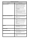
G. THERMOSTAT REPLACEMENT
Primary Thermostat (see figure11)
1. Disconnect the power cord from both the electrical outlet
and the IEC plug located at the rear of the brewer (see
figure 5).
2. Remove the hot tank assembly from the outer cabinet (see
section C).
3. Remove both wires from the anti boil thermostat.
4. Loosen tie wire and remove the rear half of the insulation
from the hot tank.
5. Using an 11/32
inch nut driver, remove nut from thermostat
threaded weld stud. Nut secures thermostat and cover.
6. Remove thermostat cover.
7. Remove thermostat from threaded weld stud.
8. Remove both wires from thermostat.
9. Replace using the reverse order as above.
NOTE: When threading the nut back to the weld stud (the
reverse of step 5) a torque value of 18 inch pounds must be
applied for proper assembly.
A
nt
i
-Boil Thermostat (see figure 11)
1. Follow steps (1-4) from Primary Thermostat.
2. Using a ¼ inch nut driver remove both screws from bracket.
3. Replace using the reverse order.
Figure 9
Mechanical Float Cap Assembly
Figure 10
Dump Solenoid Valve
Loosen Solenoid
Screws (2)
Limite
r
Control
Primar
y
Thermostat
Primary Thermostat
Cove
r
A
nti-Boil
Thermostat
Figure 11
Thermostat Locations
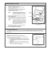
Figure 8
Open Cover
Safety float
re-set button
Air filte
r
Circuit Board
Solenoid
Valve
Spray Head
Tube