


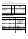
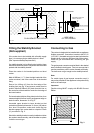


19
115
780
420
A
C
D
E
B
Installation
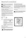
Fig. 1
Positioning the Appliance (Fig. 1)
- Note A: The appliance is designed to be flush fitted
with 2mm clearance at each side to allow for it to be
pulled forward for cleaning etc.
- Note B: The hotplate side trims should be flush with
the cabinets and must not be below. Adjustable
levelling feet at the front and rear are provided on the
base of the appliance. Adjustment is obtained by
rotating in or out, the feet at the front or rear of the
appliance from the underside of the appliance, with
the drawer removed.
A spirit level should be placed on a cake tray on one
of the shelves to confirm that the appliance is correctly
levelled. The levelling feet fitted to the appliance will
achieve a height to hotplate trims of 900mm-0 + 10.
- Note C: If the appliance is fitted next to a side wall or
cabinets above height of the hotplate trims, then a
gap of 115 mm is required.
Curtains must not be fitted immediately behind the
cooker or within 115 mm of the sides of the cooker.
- Note D: Any wall cabinet or extractor must not be
lower than 780mm above hotplate level.
- Note E: Wall cabinets may be fitted in line with the
sides of the base units, providing that the lower edge
of the wall cabinet is a minimum of 420mm above the
worktop.
The appliance must be installed in accordance to the
type X (standard EN 60335-2-6).
Therefore the appliance can not be installed beside
furniture higher than the cooker worktop.
This cooker must only be installed by qualified
personnel, according to the manufacturers instructions
and to the relevant British Standards.
FO 2599
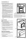
Feet Assembly
Before installing the cooker, it is necessary to
assemble the supplied feet.
1. Remove the hob pan supports, the burner caps and
crowns and the oven accessories.
2. Carefully lean the cooker on its back (Fig. 2), paying
attention not to cause any damage.
3. Adjust the feet height by unscrewing the bottom part
of each foot, until you obtain the required height (height
can be adjusted from 850 to 880 mm).
4. Insert the feet into the relevant holes indicated in fig.
2.
5. Lift the cooker in vertical position. Replace the crowns,
the burner caps, the hob pan supports and the oven
accessories.
6. If necessary, adjust the cooker horizontal levelling by
turning the bottom part of the feet, until the appliance
is completely stable.
Splash back Assembly
A splash back is supplied with the appliance. This is
meant to be fitted on the rear edge of the cookers hob.
The splash back is found in the oven cavity.
1. Carefully clean the hob top.
2. Take the splash back out of the envelope and remove
the protective film.
3. Insert the splash back into the proper hinges in the
rear part of the hob (Fig. 3).
FO 2283
FO 2376
Fig. 2
Fig. 3