


1-10
AB
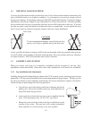
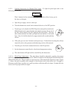
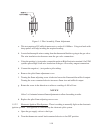
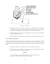
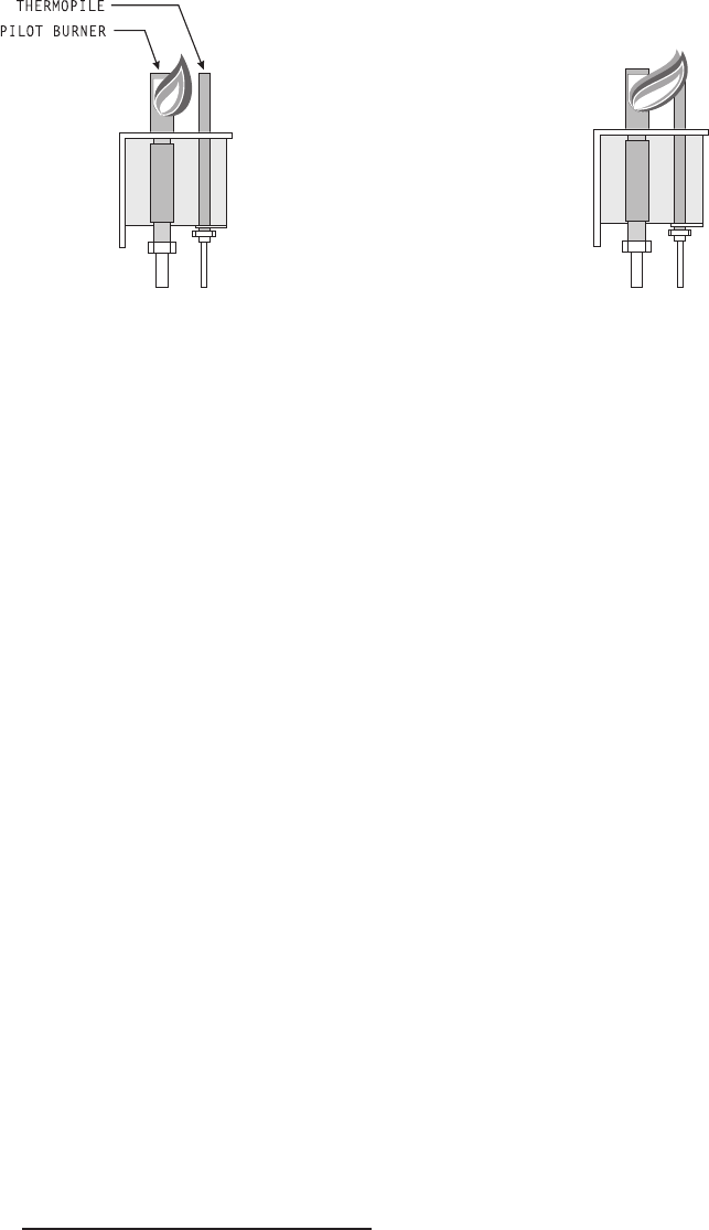
Figure 1-1 Pilot Assembly, Flame Adjustment
a. This test requires a DC millivolt meter set to a scale of 0-1000mv. Using test leads with
sharp probes will help in taking the required reading.
b. Locate the thermopile wires coming from the thermostat/limit box going to the gas valve.
The wire insulation size decreases near the gas valve connections.
c. Using the positive (+) test probe, connect the probe to High Limit wire terminal. On UFM
systems pierce High Limit wire insulation at the gas valve safety magnet connection.
d. Connect the negative (-) test probe to pilot tubing.
e. Remove the pilot flame adjustment cover.
f. Turning the flame adjusting screw clockwise lowers the flame and the millivolt output.
Turning the screw counterclockwise increases flame size and millivolt output.
g. Rotate the screw in the direction to achieve a reading of 400 ±50 mv.
NOTICE
Allow 3 to 5 minutes between flame adjustments to allow the reading to settle.
h. Replace the pilot flame adjusting screw cover.
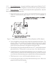
1.5.2.2 Electronic Ignition Pilot Systems - There is nothing to manually light on the electronic
ignition systems. Pilot ignition is controlled by the electronic pilot system.
a. Open the gas supply valves to the fryer.
b. Turn the thermostat control knob counterclockwise to the OFF position.