


3-6
l. Replace the two (2) nuts and tighten them.
m. Reconnect the wires.
n. Replace the limit control bulb clamp.
o. Replace the element support bar.
p. Reinstall the front panel.
q. Reconnect the cooker to the power source.
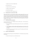
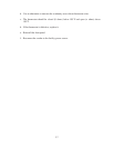
3.4 TESTING RELAYS AND CONTACTORS
Contactors and relays use a control voltage to energize an electro magnet which closes a set of
contacts. The control voltage is applied to a solenoid type coil. When measuring a coil's resistance,
ensure the coil is disconnected from the cooker's electrical system. This will ensure that only the coil's
resistance is measured and not a part of the cooker's wiring. When measured with an Ohmmeter,
these coils should have low resistance of less than 100 ohms. Measure each of the contactors that
are suspect. If any relay or contactor coil indicates an open circuit or high amount of resistance,
replace the relay or contactor.
3.5 TESTING HEATING ELEMENTS
To test a heating element, place the POWER switch in the OFF position. Test the elements by
performing the following steps:
a. The terminal block that connects the heating element to the cooker is located behind the
front panel.
b. Use an ohmmeter to check the continuity of the element from one end to the other. The
reading should be very low (a few ohms). If the element indicates an open circuit, replace
the element.
c. Next check from the hot side of the element to ground. The reading should be infinite.
If it is not, replace the element.
3.6 TESTING THE THERMOSTAT
To test the thermostat, place the power switch in the OFF position. Test the thermostat by performing
the following:
a. Remove the front panel to access the thermostat wires.