


EN
6
6
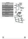
INSTALLATION
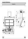
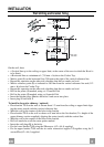
Wall drilling and bracket fixing
7.2.1
X
1÷2
11a
11
12a
112+A
A=Min 250
Max 400
710+A
1
2
1
2
200
200
180
180
A
7.3
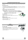
On the wall, draw
• a Vertical line up to the ceiling or upper limit, at the centre of the area in which the Hood is
to be fitted;
• a Horizontal line at a minimum of (710 mm + A) above the Cooker Top.
• Mark a point (1) on the horizontal line, 200 mm to the right of the vertical reference line.
• Repeat this operation on the other side, checking that the two marks are level.
• Mark a reference point (2) as indicated at 180 mm from the vertical reference line and (112
mm + A) above the Cooker Top.
• Repeat this operation on the other side, checking that the two marks are level.
• Drill at the points (1) marked, using a ø 12 mm drill bit.
• Drill at the points (2) marked, using a ø 8 mm drill bit.
• Insert the bracket plugs 11a into the holes 1 and screw into place.
• Insert plug 11 into hole 2.
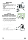
To install a decorative chimney ( optional )
• Place bracket 7.2.1 on the wall as shown about 1-2 mm from the ceiling or upper limit align-
ing the centre (notch) with the vertical reference line.
• Mark the wall at the centres of the holes in the bracket.
• Place bracket 7.2.1 on the wall as shown at X mm below the first bracket (X = height of the
upper chimney section supplied), aligning the centre (notch) with the vertical line.
• Mark the wall at the centres of the holes in the bracket.
• Drill ø 8 mm holes at all the centre points marked.
• Insert the wall plugs 11 in the holes.
• Fix the lower bracket 7.2.1 using the 12a screws (4,2 x 44,4) supplied.
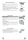
• Fix the upper bracket 7.2.1 and the air outlet connection support 7.3 together using the 2
screws 12a (4,2 x 44,4) supplied.