


13
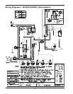
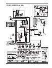
Sequence of Operation
On call for heat, the D-2 Power Vent fan (and appli-
ance pump) start. When the flow switch circuits close,
the ignition system consisting of an electronic spark
module, pilot gas system and flame sensor, are ener-
gized. When draft proving switch closes and all safety
circuits are proven, the automatic main gas valves will
open and the heater will operate. When the operating
limit circuit is satisfied, the heater will shut down.
Start Up Procedures
The water system, the gas system and the electrical
system for the heater should be completed and
checked as per the heater installation manual and
associated documents.
1. Turn on power to the heater with the manual main
gas valve and pilot gas valve off. The electric power
supply requirements are:
a. Dual-voltage fan motor.
120/240 volt 60Hz 1.0/1.95 Amp fan
motor for models 181-401.
2. Check power connections.
3. Close heater power switch.
4. Set operating control to call for heat.
a. Fan motor starts, draft proving switch clos-
es.
b. Heater pump starts, flow switch closes.
c. Ignition module energized.
d. Check for spark at gas pilot.
5. Turn operating control to end call for heat.
6. Wait a minimum of 60 seconds.
7. Open pilot gas valve.
a. Repeat procedure outlined in #4 above.
8. After pilot gas is proven and main safety shut-off
valve is energized.
a. Main burners will ignite.
9. Heater will operate until call for heat is satisfied.
10. Restart unit and visually check all components for
proper operation.
11. Check all vent connections and joints for leakage.
Correct if found.
12. To restart unit after a failure, follow the procedures
outlined above and other subsequent or related sec-
tions outlined in the heater manual.
EMERGENCY SHUTDOWN: SHUT OFF ALL
POWER AND GAS, CALL GAS UTILITY.
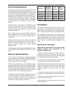
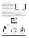
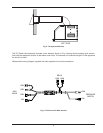
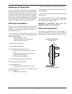
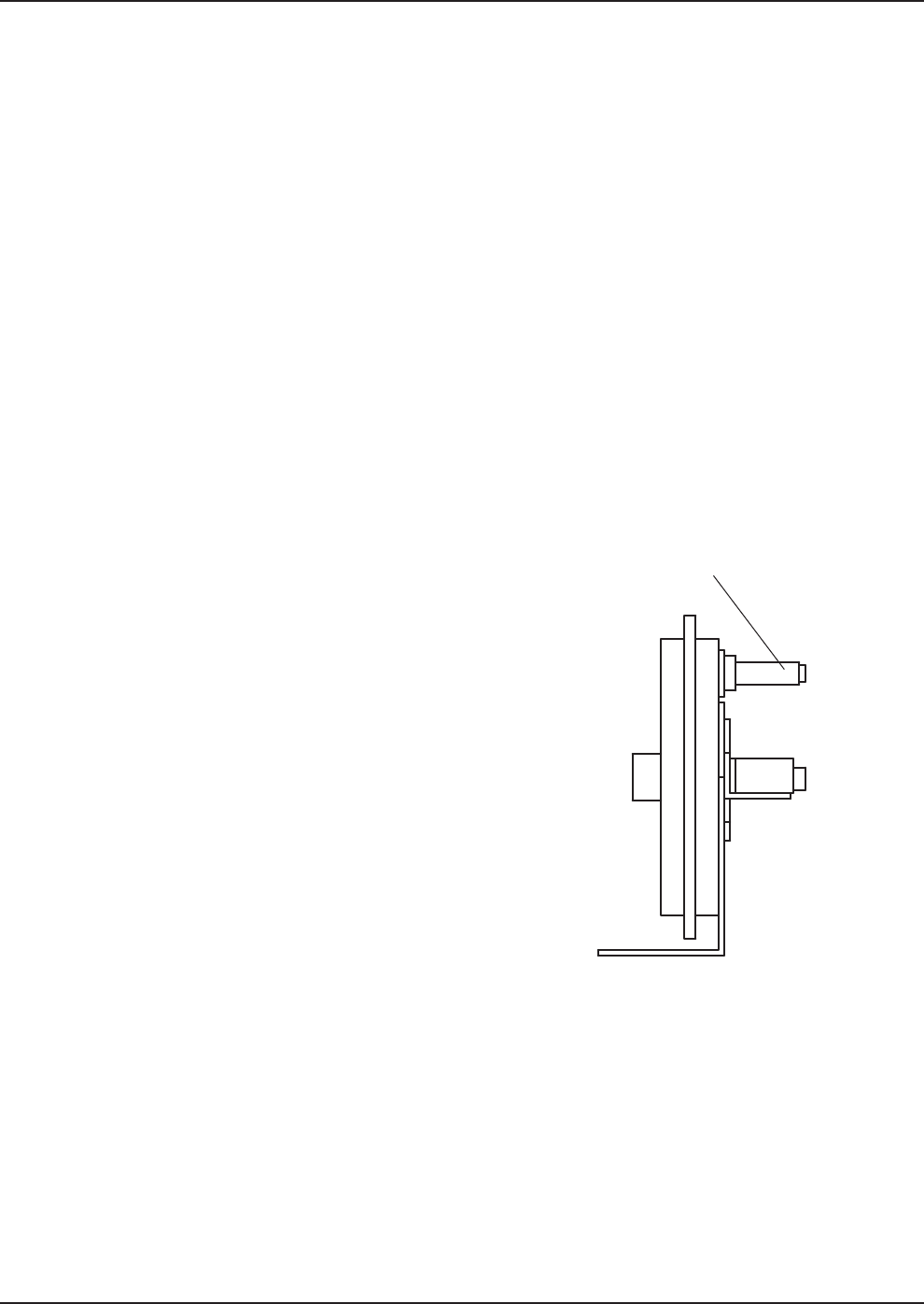
Draft Proving Switch
The draft proving switch insures that the blower is
operating. The switch is in the limit circuit and does not
allow the ignition module to operate unless it is closed.
NEGATIVE PRESSURE
CONNECTOR
Fig. 7: Draft Proving Switch