


6
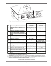
7. Mount the Power Vent on the outer top.
8. Route the conduit harness of the Power Vent thru
the outer top hole, around the adapter towards the
back of the unit. Continue routing the harness thru the
corner slot, which leads to open area behind the
access panel. Finally, route only the wire harness thru
the 7/8” grommet hole located on the sway brace.
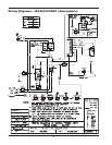
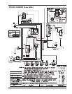
Follow instructions on page 7 to wire the Power Vent.
Note: Newer units have a 7/8” grommet located on the
rain shield, which would eliminate routing the harness
around the back corner.
9. Re-mount the jacket top to its original position and
screw in the four screws holding it down to the appli-
ance.
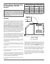
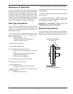
10. If the appliance is a 181, 182, 330 or 331, remove
the tabs underneath the power vent using a 5/16” nut
driver and relocate them closer to the center of the
Power Vent as shown in Fig. 1.
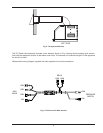
11. Mount the Power Vent assembly bottom on the 6”
vent as shown below. Twist the assembly downward.
Snap the mounting brackets into their appropriate slot
to hold the Power Vent in position. Note: While twisting
you may notice some roughness, this is due to a tight
seal between the 6” vent and the Power Vent flue box.
12. Re-mount the access panel.
13. Re-mount the front door along with the knurled
screw on the heater.
TABS
BEFORE AFTER
Fig. 1: Reposition the Tabs as Necessary (see step 10)
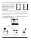
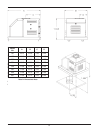
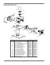
Fig. 2: Draft Assembly
TOP VIEW
LEFT SIDE FRONT VIEWREAR VIEW
EXHUAST
OUTLET
Note: The 90° elbow may be used as a termination cap.