


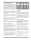


Receiving Equipment
On receipt of your equipment it is suggested that you
visually check for external damage to the carton. If the
carton is damaged, it is suggested that a note be made
on the Bill of Lading when signing for equipment.
Remove the complete assembly from the carton if it is
damaged report the damage to the carrier immediate-
ly. Be sure that you receive the number of packages
indicated on the Bill of Lading. Claims for shortages
and damages must be filed with the carrier by con-
signee.
Purchased parts are subject to replacement only
under the manufacturer's warranty. Debits for defec-
tive replacement parts will not be accepted and
defective parts will be replaced in kind only per our
standard warranties.
When ordering parts, you must specify Model and
Serial Number of the unit. When ordering under war-
ranty conditions, you must also specify date of
Installation.
Raypak recommends that this manual be reviewed
thoroughly before installing the D-2 Power Vent. If
there are any questions which this manual does not
answer, please contact your local Raypak
Representative.
THIS MANUAL SHOULD BE MAINTAINED IN LEGI-
BLE CONDITION AND KEPT ADJACENT TO THE
UNIT.
General Specifications
The D-2 Power Vent Assembly is tested and certified
to the latest edition of the American National Standard
ANSI Z21.56. standard for pool heaters, Z21.10.3 for
water heaters and Z21.13 for boilers.
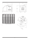
The Power Vent Assembly is a fan assisted combus-
tion system designed for application to Raypak Heater
Models 181-401. The unit, when installed as directed,
is capable of operating in applications such as through
the wall venting and reduced horizontal and vertical
vent pipe sizes in new and existing installations.
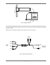
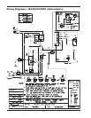
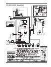
The D-2 Power Vent assembly includes a blower with
a 120/240 volt 60 Hz 1.0/1.95A 3200 RPM motor, a
plenum complete with a draft proving switch and a
motor relay. When provided for field mounting the
assembly is equipped with a wire harness.
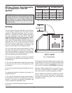
Installation
The equipment must be installed in accordance with
local codes, or in the absence of local codes with the
latest edition of the National Fuel Gas Code, ANSI
Z223.1, the National Electrical Code, ANSI/NFPA 70.
The equipment shall be installed in accordance with
those installation regulations in force in the local area
where the installation is to be made. These shall be
carefully followed in all cases. Authorities having juris-
diction shall be consulted before installations are
made.
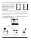
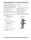
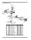
Mounting the Assembly
Follow these instructions if the Power Vent
venting system was purchased as an
optional assembly kit.
1. Remove existing pagoda top (outdoor units) or
drafthood (indoor units). To remove the pagoda top,
push the four brackets inward and pull up the pagoda
top. The pagoda may then be discarded.
2. Unscrew the four screws holding the outer top using
a phillips screw driver. Remove the jacket top.
3. Replace the inner stack adapter. If the heater had a
drafthood installed previously, remove the inner stack
adapter and replace it with the Power Vent stack
adapter. Otherwise, install the Power Vent stack
adapter.
4. Unscrew the access panel on the right side of the
appliance. Set aside the screws with the access panel.
5. Remove the knurled screw holding the front door
and set it aside with the door.
6. Mount the jacket top above the unit. Note: Do not
install at this point.
5
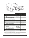
Table A: Draft Assembly Application and Kit Numbers
Model No.
Minimum
Connection
Diameter
Kit
Number
Factory
Wired
181/182 4” 008757 120V
260/261 4” 008757 120V
330/331 4” 008758 120V
400/401 4” 008758 120V