


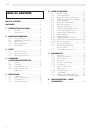

English
7
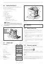
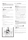
150 mm
100 mm
60 mm
21
23
24
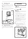
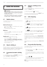
fig. 4
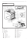
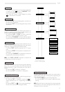
4.4 Steam/hot water spout (LUXE version)
The steam (ref. 16, fig. 1) and hot water spouts (ref. 11, fig. 1)
are equipped with suitable rubber protectors (ref. 14 and 9, fig.
1) so that they can be easily gripped and moved even when over-
heated.
5 - INSTALLATION
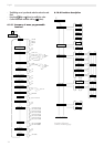
4.3 Coffee dispenser unit
The position of this unit (ref. 21, fig. 4) can be modified accord-
ing to the height of the container used.
In fact it is possible to move the mobile dispenser backwards (ref.
23, fig. 4) and the telescopic dispenser upwards or downwards
(ref. 24, fig. 4).
This allows different heights to be obtained.(see fig. 4).
N.B.: If a container taller than 90 mm is always and exclusively
used, the telescopic dispenser can be removed altogether (ref.
23, fig. 4), by drawing it downwards.
Danger
Operation falling within the competence of the Maintenance
technician.
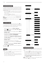
5.1 Connections
Warning
The connection will have to be implemented by observing the
national safety rules
Carry out connections as follows:
- Check that the surface upon which the machine is placed is
firm and able to withstand the weight.
- Drill the relevant holes in the surface top (ref. C’ and D’ or F’,
fig. 6), and possibly also the other holes (ref. B’, fig. 6 e ref.
E’, fig. 6 - see N.B.), as indicated in the drawing.
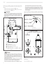
- Install the machine on the surface and level it by adjusting the
feet made available for this operation (ref. A, fig. 5).
- Connect machine to the drinking water system by way of the
special fitting (ref. C, fig. 5).
WATER AND WASTE CONNECTIONS SHALL COMPLHY
WITH APPLICABLE FEDERAL STATES, OR LOCAL CODES.
(Only for USA and CDN models)
- Connect to the power mains by way of the relevant cord (ref.
D, fig. 5).
N.B.: It is possible to connect the drip tray (ref. 15, fig. 1)
directly to an outlet by proceeding as follows:
- drill the surface top as indicated (ref. B’, fig. 6);
- break the removable diaphragm which seals the drip tray
outlet (ref. 15, fig. 1);
- join a drain tube to the fitting (ref. B, fig. 5), by way of a
suitable hose clamp.
fig. 5
A
B
C
D
A
A
A
E