10
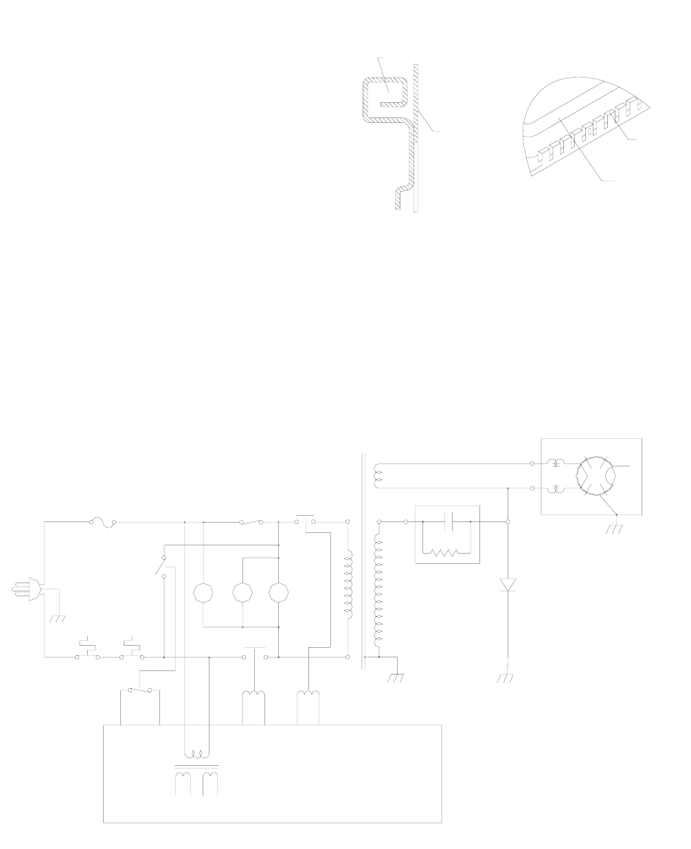
front door plate
Fig.2-9
current-resistant
constructure
oven door
noise filter
8). It is the most liable place where microwave leakage occurs. Especially, after a long time using, the microwave
leakage would enlarge at the hinge and the hook. Anyway, mechanic damage would also cause large amount of
microwave leakage. Therefore, the main methods designed for preventing microwave leakage of the door are as
follows:
1) Assemble a layer of steel filament or a thin metal plate with many holes at the middle of the window to made it
is possible to observe the heating as well as shielding the microwave.
2) The widely used seal measurement at present
is to assemble a current – resistant construct
between the door and the doorframe. FIG.2-9 is
the typical construction fig of the door. It was
designed according to the theory of
“THETRANSFERING LINE ONE–FOURTHWAVE
LENGTH IMPEDANCE CHANGER”. Although
there is no connecting point from a mechanical
point. It is sealed at the seam from the point of
electricity, so it is called “CURRENT-RESISTANT”.
Recently, with the installation of noise filter in the
current resistant trough, the effect to restrain the
microwave leakage (include high subharmonic)
have been much improved.
3
3
.
.
T
T
Y
Y
P
P
I
I
C
C
A
A
L
L
C
C
I
I
R
R
C
C
U
U
I
I
T
T
A
A
N
N
A
A
L
L
Y
Y
A
A
S
S
I
I
S
S
O
O
F
F
M
M
I
I
C
C
R
R
O
O
W
W
A
A
V
V
E
E
O
O
V
V
E
E
N
N
We have introduced the structure and the working principle of the microwave oven previously. We shall analyze
the complete set circuit of the microwave oven link with the practical circuit at this chapter.
TRANSFORMER
VOLTAGE
SWITCH
DIGITAL PROGRAMMER CIRCUIT
TRANSFORMER
LOW VOLTAGE
MONITOR
60Hz
120V
SECONDARY
(MAG.)
N
L
CUTOUT
THERMAL
(OVEN)
SWITCH
FUSE
SWITCH
SCHEMATIC DIAGRAM
NOTE: Door is closed
Unit is not operated
PRIMARY
LAMP
OVEN
L
FM
MAIN
RELAY
MOTOR
FAN
POWER
MT
RELAY
MOTOR
TABLE
TURN-
HIGH
C
CAPACITOR
DIODE
HIGH
HIGH
VOLTAGE
VOLTAGE
MAGNETRON
F
FA


