11
Fig.3–1 is the practical circuit diagram of a microwave oven. Its corresponding working conditions are as follows:
The door closed, SW1 and SW2 turned on, SW3 closed, power control relay has no power, R1, R2 is cut off.
When cooking, touch the starting switch to power the timer and the power relay. RY1, RY2 closed the power
supply to the anode of the magnetron and the filament, changing the power frequency electric energy to
microwave energy, the microwave energy then transferred to the heating chamber for food heating. At the same
time, the lamp turned on, the fan motor begins to cool the magnetron. The turntable motor set off to drive the food
around and making the food heated evenly. The microcomputer begins reckon the time, when it reached the sets
time, power relay are cut off, the power of the lamp, all the motor and the magnetron are cut off, the food –
heating process ended. During the heating, if the door was opened, the interlock S1, S2 will cut off, S3 will close,
all the motors and the magnetron will also be cut off, the lamp will turn on, the oven stop heating immediately. If
heating need go on, just push down the starting button and closed the door, the oven will continue its working.
When something wrong with the fan motor or the air vent was blocked that breakdown the cooling system, the
magnetron temperature would rise high very quickly. When the temperature reached the working point of the
thermal cutout (S6), S6 will be cut off immediately to cut off the power supply to the magnetron and the
magnetron will stops working right away. The PC board is cut off to prevent the magnetron from being damaged
by overheating. When the thermal cutout is cut off, the magnetron, motors and the lamp would stop working
simultaneously. Moreover, the thermal cutout has the self - resuming character, when the temperature lowered, it
will resume to close condition.
Circuit diagram of computer controlled microwave ovens:
Circuit diagram for mechanical controlled microwave ovens:
4
4
.
.
H
H
O
O
W
W
T
T
O
O
A
A
S
S
S
S
E
E
M
M
B
B
L
L
E
E
A
A
N
N
D
D
D
D
I
I
S
S
A
A
S
S
S
S
E
E
M
M
B
B
L
L
E
E
M
M
I
I
C
C
R
R
O
O
W
W
A
A
V
V
E
E
O
O
V
V
E
E
N
N
C
C
O
O
M
M
P
P
O
O
N
N
E
E
N
N
T
T
S
S
In the following pages, we will introduce the ways in which the various parts of a typical microwave oven can be
disassembled and assembled.
4
4
.
.
1
1
T
T
H
H
E
E
C
C
A
A
B
B
I
I
N
N
E
E
T
T
To disassemble the cabinet
1. Pull out the power plug.
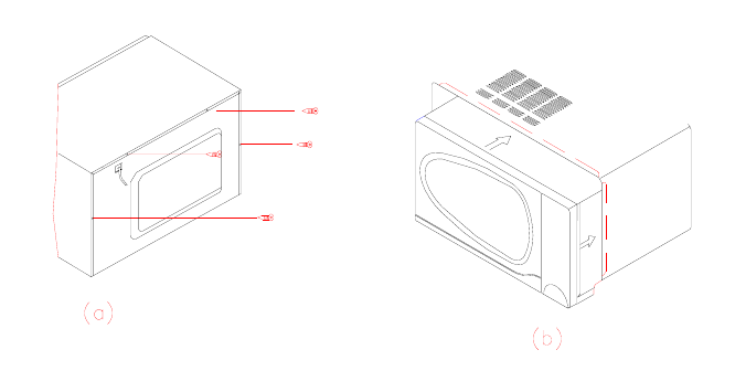
2. Loosen the four screws at the back of the oven with a “+”- screwdriver. (FIG.4-1a)
3. Push the cabinet back 25mm according to the arrow direction shown at FIG.4-1 (b), and the cabinet can be
taken off.
To assemble the cabinet
1. Put the cabinet on the oven, and push it full ahead.
2. Check whether the up, right and left troughs have been inserted with the curved with the curved rim of the
oven (FIG.4-1 (b)). If the cabinet and the oven are not tallied exactly, then it should be reassembled or those
untallied parts should be smoothed.
3. Tighten those four screws, please make sure that one of the screws should have a plum blossom shape
washer to keep a good earth.


