


O
WNER
’
S
M
ANUAL
1190820
REV
3
(11/10) P
AGE
27
OF
48
A
DJUSTMENT OF
O
PEN
-T
OP
P
ILOTS
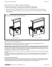
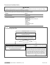
The open-top pilots are the non-aerated (yellow-tipped flame) type. One is located beside each open-top burner.
Pilot outage is often caused by an unstable flame due to over-adjustment to the point where the flame is leaving its
port, or “blowing off.” Often, in an effort to improve ignition, the pilots are increased too much and result in this
unstable condition.
The pilots are adjusted by inserting the blade of a screwdriver into the slot on the small valve, located on the manifold.
The maximum flame size is approximately 3/4" (19 mm) with a slight yellow tip. The first indication of over-adjustment
is evident when the yellow tip begins to stream into black streaks and generate carbon. Continued over-adjustment
leads to the unstable lifting and blowing condition.
A
DJUSTMENT OF
O
PEN
-T
OP
B
URNERS
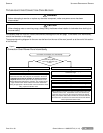
All open-top burners are primarily adjusted by means of an air shutter on the mixer face.
To adjust a burner, loosen the screw that holds the air shutter in position and rotate the mixer cap until a clear, stable
blue flame is obtained. The flame should not be yellow tipped nor should it blow off the burner ports.
All orifice sizes and burner rate are properly set at the factory and should not be altered.
Over-rated burners cause poor burner and pilot performance, resulting in less heat, and wasted gas.
A
DJUSTMENT OF
G
AS
O
VEN
S
TANDING
P
ILOT
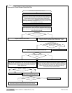
The standing oven pilot flame can be adjusted by turning the adjusting screw on the pilot line valve with a screwdriver.
The pilot line valve is located behind the kick panel below the oven door. Remove the kick panel to gain access. The
pilot flame is properly adjusted when it is just large enough to maintain a glowing red color of the thermopile capillary
bulb.
A
DJUSTMENT OF
G
AS
O
VEN
B
URNER
The oven burner orifice is of the fixed type, sized for the specified gas supply. The burner flame characteristics are
controlled by varying the primary air mixer cap. There should be a clear blue flame with a distinct inner cone at each
port. Excessive primary air can result in “blowing” or the flames leaving the ports. Lack of primary air causes soft or
yellow tipped flame.
A
DJUSTMENT OF
C
HARBROILER
,
S
TANDARD
-G
RIDDLE
,
AND
U
NIFORM
H
OT
-T
OP
B
URNERS
AND
P
ILOTS
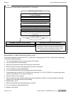
The burner valves are not adjustable. The burner orifice is of the fixed type, sized for the type of gas and the operating
altitude. To adjust the burner air-gas mixture, loosen the screw that secures the air shutter on the mixer face and
rotate the mixer cap to obtain a clear, stable blue flame with a distinct inner cone at each port. Excessive primary air
causes “blowing” (the flames leaving the ports), while insufficient primary air causes a soft or yellow tipped flame.
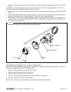
The pilots are near the front of the burners, and are held in position by brackets. To adjust a pilot flame, insert a
screwdriver through the opening in the valve panel between the control knobs and turn the appropriate pilot
adjustment screw counterclockwise to increase the size of the pilot flame, or clockwise to decrease the size of the
pilot flame. The maximum flame size is approximately 3/4" with a slight yellow tip. The first indication of over-
adjustment is when the flame tip becomes more yellow and begins to generate carbon, which appears as rising black
streaks. Continued over-adjustment leads to unstable lifting and a blowing condition.