


PLATINUM SERIES SECTIONAL RANGE INSTALLATION
INSTALL AND OPERATIONS MANUAL 1185836 REV 3 (07/06) PAGE 27 OF 80
STEP 2C: MOUNT RANGE ON CASTER FRAME
NOTICE
For an appliance equipped with casters, (1) the installation shall be made with a connector that complies with the
Standard for Connectors for Movable Gas Appliances, ANSI Z21.69 or Connectors for Moveable Gas Appliances,
CAN/CGA-6.16, and a quick-disconnect device that complies with the Standard for Quick-Disconnect Devices for
Use With Gas Fuel, ANSI Z21.41, or Quick Disconnect Devices for Use with Gas Fuel, CAN1-6.9, (2) adequate
means must be provided to limit the movement of the appliance without depending on the connector and the
quick-disconnect device or its associated piping to limit the appliance movement and (3) the restraining means
should be attached to a frame member on the back of the unit.
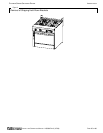
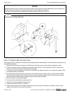
The range can be mounted on an optional caster frame. The frame will have a threaded leg pad at each corner. Each
caster has a corresponding mating thread. The casters can be adjusted to overcome a slightly uneven floor. Casters
are provided with a Zerk fitting for proper lubrication when required.
1. Assemble the caster frame components.
2. Screw the casters into the holes in the centers of the leg pads of the caster frame. Install the casters that have a
locking brake under the front of the battery.
3. Lower the caster frame gently onto a level surface. Never drop or allow the frame to fall.
4. Block and brace the frame so that it will not move while the battery sections are installed on it.
5. Lift and gently place the range in position on the caster frame. Never drop or allow the range to fall.
6. Bolt the range to the caster frame.
7. Go to Installation Step 3.
STEP 3: ATTACH RESTRAINT TO RANGE (OR BATTERY) MOUNTED ON CASTERS
NOTICE
For an appliance equipped with casters, (1) the installation shall be made with a connector that complies with the
Standard for Connectors for Movable Gas Appliances, ANSI Z21.69 or Connectors for Moveable Gas Appliances,
CAN/CGA-6.16, and a quick-disconnect device that complies with the Standard for Quick-Disconnect Devices for
Use With Gas Fuel, ANSI Z21.41, or Quick Disconnect Devices for Use with Gas Fuel, CAN1-6.9, (2) adequate
means must be provided to limit the movement of the appliance without depending on the connector and the
quick-disconnect device or its associated piping to limit the appliance movement and (3) the restraining means
should be attached to a frame member on the back of the unit.
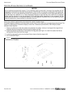
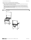
Install the restraint cable to a range (or battery) mounted on casters using the following procedure:
1. Secure the restraining-device bracket (item “B” in Figure 15) to a wall stud located as close as possible to the
appliance connector inlet and outlet connections. Use four #12 screws (items “C”) and plastic anchors (items “A”)
if necessary.
2. Install eye-bolt (item “F”) to a frame member on the rear of the equipment. After checking carefully behind the
frame member for adequate clearance, drill a 1/4" hole through the frame member.
3. Thread hex nut (item “G”) and slide the washer (item “H”) onto the eye-bolt. Insert the eye-bolt through the 1/4"
drilled hole and secure with a washer (item “H”) and nylon lock nut (item “I”).
4. Using the spring-loaded snap hooks, attach the restraining device to the bracket and the eye-bolt.
5. Using the cable clamp (item “D”), adjust the restraining device extended length to prevent over-bending or
kinking of the appliance connector.
For units not equipped with flame safety devices, be sure all valves are turned off prior to disconnecting. After
reconnecting, be sure all control knobs are turned off and all pilots are lit.