


PLATINUM SERIES SECTIONAL RANGE SERVICE
INSTALL AND OPERATIONS MANUAL 1185836 REV 3 (07/06) PAGE 39 OF 80
Fi
g
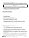
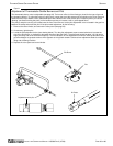
ure 21
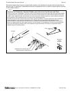
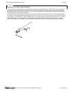
Adjustment of Thermostatic-Griddle Burners and Pilot
The thermostatic burner valve is adjustable (see page 38). The burner orifice is of the fixed type, sized for the type of gas and
the operating altitude. To adjust the burner air-gas mixture, loosen the screw that secures the air shutter on the mixer face and
rotate the mixer cap to obtain a clear, stable blue flame with a distinct inner cone at each port. Excessive primary air causes
“blowing” (the flames leaving the ports), while insufficient primary air causes a soft or yellow tipped flame.
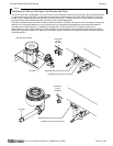
The pilot(s) and pilot-runner(s) are located near the front of the burners, but the pilot adjustment valve is located in the gas line
between the safety switch and the pilot. If the pilot needs adjustment, do the following:
1. Remove the control knobs, and remove the valve panel (see page 33).
2. If necessary, light the pilot.
3. Locate the pilot adjustment valve (see drawing below). Turn the pilot adjustment screw counterclockwise to increase the
size of the pilot flame, or clockwise to decrease the size of the pilot flame. The pilot flame should be about 1/2" high with a
slight yellow tip, and cover the thermocouple tip. The first indication of over-adjustment is when the flame tip becomes more
yellow and begins to generate carbon, which appears as rising black streaks. Continued over-adjustment leads to unstable
lifting and a blowing condition.
4. Replace the valve panel and control knobs.
Adjustment screw for pilot
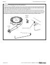
Air Shutter
Pilot
Pilot Runner