


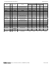
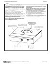
PLATINUM SERIES SECTIONAL RANGE SPECIFICATIONS
INSTALL AND OPERATIONS MANUAL 1185836 REV 3 (07/06) PAGE 5 OF 80
VENTILATION
WARNING
Improper ventilation can result in personal injury or death. Ventilation which fails to properly remove flue products
can cause headaches, drowsiness, nausea, or could result in death.
All gas appliances must be installed in such a manner that the flow of combustion and ventilation air is not
obstructed. Provisions for adequate air supply must be provided. Do not obstruct the area under the control panel
or below the oven door (on the front), or the area below the flue riser (on the back) as combustion air enters
through these areas.
NOTICE
Proper ventilation is the owner’s responsibility. Any problem due to improper ventilation will not be covered by the
warranty.
Be sure to inspect and clean the ventilation system according to the ventilation equipment manufacturer’s
instructions.
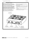
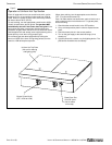
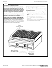
Air for combustion enters from the front below the valve panel, as well as from the rear into the burner box. Ranges
with solid tops (griddles and hot-tops) vent their flue products up the flue riser. On units with a base oven, combustion
air enters from the front below the oven door. Oven flue products are vented up the flue riser.
Lack of sufficient ventilation will cause poor burner and pilot operating characteristics, resulting in inefficient
performance. Such conditions also cause high ambient temperatures at the manifold area and create valve and
thermostat problems.
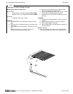
If a ventilation canopy is used, it is recommended that the canopy extend 6" past the sectional range and that the
bottom edge be located 6'6" from the floor. Filters should be installed at an angle of 45° or more from the horizontal.
This position prevents dripping grease, and facilitates collecting the run-off grease in a drip pan under the filter.
A strong exhaust fan tends to create a vacuum in the room and may interfere with burner performance or may
extinguish pilot flames. Fresh air openings approximately equal to the fan area will relieve such a vacuum. The
exhaust fan should be installed at least 2" above the top of the flue riser.
If the sectional range is connected directly to an outside flue, a CSA design certified down draft diverter must be
installed.
In case of unsatisfactory performance by any gas appliance, check the appliance with the exhaust fan turned OFF. Do
this only long enough to check whether doing so corrects any problems with equipment performance. Then turn the
exhaust fan back on and let it run to remove any exhaust that may have accumulated during the test.
GAS SUPPLY
The sectional range is design-certified for operation on natural or propane gases. The sectional range is shipped
configured and adjusted for the type of gas specified by the purchaser, which is indicated on the serial plate (see
Figure 1 on page 3). Connect the sectional range ONLY to the type of gas for which it is configured and adjusted.
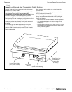
Each section has a 1-1/4" front gas manifold that can be coupled to adjacent section(s). Sections can be ordered with
an optional 1" rear gas connection with a male NPT connector. Minimum supply pressure is 7" W.C. for natural gas,
11" W.C. for propane. An external pressure regulator and shut off valve must be provided. If using a flexible-hose gas
connection, the I.D. of the hose must not be smaller than the connector on the unit and must comply with ANSI
Z21.69. Provide an adequate means of restraint to prevent undue strain on the gas connection.
If applicable, the vent line from the gas appliance pressure regulator shall be installed to the outdoors in accordance
with local codes, or in the absence of local codes, with the National Fuel Gas Code, ANSI Z223.1, Natural Gas
Installation Code, CAN/CGA-B149.1, or the Propane Installation Code CAN/CGA-B149.2, as applicable.
An adequate gas supply is imperative. Undersized or low pressure lines will restrict the volume of gas required for
satisfactory performance. Fluctuations of more than 25% on natural gas or 10% on propane gas will create problems
and affect burner operating characteristics. A 1/8" pressure tap is located on the manifold to measure the manifold
pressure. The supply line to the sectional range should be no smaller than the inside diameter of the pipe on the
sectional range to which it is connected.