Recold
/
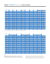
JW Series Fluid Cooler
/
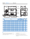
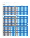
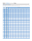
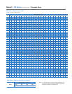
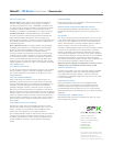
Schematic
4
A
B
G
F
C
L L
K
H
D
J
12" 2"
DRAIN AND
OVERFLOW
P
EXTERNAL
FLOAT BOX
INLET
CONNECTION
SPRAY HEADER
CLEANOUT
OUTLET
CONNECTION
12"
WATER SUPPLY Q
INLET
OUTLET
ELIMINATOR
ACCESS
ACCESS
DOOR
2" LIFTING
HOLE (4)
7
/
8
" MOUNTING
HOLE (6)
Model
Dimensions
Access Doors Overflow
Drain
FPT
Water
Supply
FPT
Far Side Near Side
A B C D F G H J K L Top Bottom Top Bottom P Q
JW10 80" 76" 31" 84" 32
1
⁄2" 19
1
⁄2" — 6" 53" 13
1
⁄2" 1 1 — — 2
1
⁄2"
1
⁄2"
JW15 96" 76" 37" 102" 31
1
⁄2" 19
1
⁄2" — 6" 65" 16 1 1 — — 2
1
⁄2"
1
⁄2"
JW25 115
3
⁄4" 77" 45
1
⁄4" 124" 34" 19
1
⁄2" 51
1
⁄4" 6 76
3
⁄4" 20
1
⁄2" 1 1 1
1
note 3
2
1
⁄2"
1
⁄2"
JW35 139
1
⁄2" 80
1
⁄4" 55
1
⁄2" 144" 38" 19
1
⁄2" 51" 6" 92" 14
1
⁄2" 1 1 1
1
note 3
2
1
⁄2"
3
⁄4"
JW50 172
1
⁄4" 92
1
⁄2" 66
7
⁄8" 180
1
⁄4" 41" 19
1
⁄2" 71
3
⁄4" 6" 115" 17
3
⁄8" 2 1 2
1
note 3
2
1
⁄2" 1"
JW70 184
1
⁄4" 98
1
⁄2" 93
1
⁄4" 192" 47" 19
1
⁄2" 84
1
⁄2" 8" 115"
note 4
2 1 2
1
note 3
3" 1
1
⁄4"
JW85 208" 98
1
⁄2" 93
3
⁄8" 217" 47" 19
1
⁄2" 96
1
⁄2" 8" 139
1
⁄4"
note 4
2 1 2
1
note 3
3" 1
1
⁄4"
JW100 221" 118
1
⁄2" 100
1
⁄2" 225" 67" 19
1
⁄2" 80" 10" 139
1
⁄2"
note 4
2 2 2
2
note 3
4" 1
1
⁄4"
JW115 245
1
⁄2" 118
1
⁄2" 100
1
⁄2" 249" 67" 19
1
⁄2" 104" 10" 164
1
⁄2"
note 4
2 2 2
2
note 3
4" 1
1
⁄4"
JW130 269" 118
1
⁄2" 100
1
⁄2" 273" 67" 19
1
⁄2" 128" 10" 188"
note 4
2 2 2
2
note 3
4" 1
1
⁄4"
Note
1 Use this bulletin for preliminary layouts only. Obtain current
drawing from your Recold sales representative.
2 If required add 6" for positive closure dampers. If required
add 6" for booster coil section.
3 An additional bottom access door is installed on the
connection end.
4. Consult Recold for coil connection locations.
5 If supporting the unit on beams, refer to the Recold
suggested supporting steel drawing for required mounting
hole location.


