Recold
/
JW Series Fluid Cooler
/
Freeze Protection
6
For the most part, evaporative closed circuit coolers
will be installed for operation on a year-round basis.
Units installed in a cold climate must be provided with
adequate freeze protection for both the recirculating
water and the heat exchange coil for proper
equipment operation and maintenance.
RECIRCULATING WATER
The operation of evaporative cooled equipment under
approximately full load conditions will prevent freezing
of the recirculated water. However, during periods of
very little or no heat load when fans and pumps are
shut down, some form of freeze protection must be
used.
A simple form of freeze protection commonly used
is a remote sump tank inside a heated building
below the evaporative cooled equipment. The water
circulation pump is located at the remote tank
circulating water through the evaporative cooler
during load conditions. When the unit is shut down,
the water drains down into the remote sump tank
which is in a heated atmosphere.
The remote sump installation may be unacceptable in
some cases due to unit location or space limitations.
For these applications, pan water freeze protection
may be attained by means of an optional electric
heater located inside the unit pan. Electric pan
heaters are designed to prevent pan water freezing
during unit shut down with fans and pumps idle.
Water lines to and from the unit, pump, pump
discharge and drain lines must be wrapped with a
heat-tracing element and insulated to protect them
from freezing.
HEAT EXCHANGE COIL PROTECTION
The best means of heat exchanger coil freeze
protection is to circulate an ethylene glycol water
solution. The solution freeze points with respective
ethylene glycol by volume are given in Table 11
below. This method will allow freeze protection
irrespective of heat load or unit shut down.
Some applications will not permit the use of an
ethylene glycol solution. Under these circumstances,
other means of freeze protections must be used and
the following rules strictly adhered to.
1. Maintain full flow through the coil
2. Maintain heat load on the coil at all time so that the
leaving water temperature does not drop below
+50°F
Full flow alone will not protect the coil.
Temperature of +50°F must also be maintained.
Methods of maintaining the recommended fluid
temperature may vary with system design and
operation. A simple means of preventing heat loss
may be to locate the unit indoors allowing a heated
atmosphere. Adequate space and ductwork must be
provided for proper operation.
Units operating in low ambient conditions with a
heat load which becomes very low or drops off
completely may require the addition of an artificial
load to maintain safe fluid temperature. The amount
of artificial load required may be reduced by means
of discharge positive closure dampers. The addition
of the dampers will prevent induced air circulation or
the chimney effect which may occur during unit shut
down.
The above methods of coil freeze protection, when
properly applied and maintained will provide good
equipment protection. All methods, other than
those using an adequate antifreeze solution, should
provide a means of emergency coil draining. It is
recommended that automatic drain valves and air
vents with vacuum breakers be installed on each
coil circuit. Adequately size drains with heat-tracing
tape and insulation should be provided for free
drainage. Should the circulating pump fail or the water
temperature leaving the coil drop below 50°F for any
reason, the coil will automatically drain preventing
freeze damage.
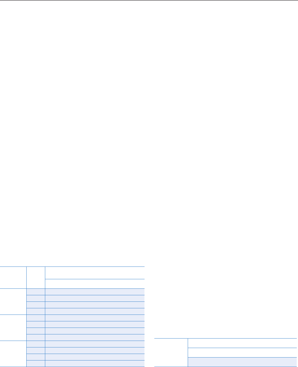
Freeze
Point °F
Ethylene Glycol (by volume)
20% 30% 40% 50%
14 3 -14 -38
Unit Model
JW/JWL
Ethylene
Glycol
By Volume
Design Flow GPM
40 50 70 90 100 125 150 175 Above
10A thru 35C
20% 1.07 1.05 1.02 1.00 1.00 1.00 1.00 1.00 1.00
30% 1.10 1.07 1.02 1.01 1.00 1.00 1.00 1.00 1.00
40% 1.14 1.11 1.05 1.01 1.00 1.00 1.00 1.00 1.00
50% 1.16 1.13 1.06 1.01 1.00 1.00 1.00 1.00 1.00
50A thru 50C
20% 1.12 1.09 1.05 1.03 1.02 1.00 1.00 1.00 1.00
30% 1.16 1.12 1.07 1.04 1.02 1.00 1.00 1.00 1.00
40% 1.19 1.16 1.11 1.06 1.04 1.01 1.00 1.00 1.00
50% 1.23 1.21 1.14 1.08 1.05 1.01 1.00 1.00 1.00
70B thru 130C
20% 1.15 1.11 1.09 1.06 1.04 1.03 1.01 1.00 1.00
30% — 1.18 1.11 1.07 1.05 1.03 1.01 1.00 1.00
40% — 1.20 1.15 1.10 1.07 1.05 1.03 1.00 1.00
50% — 1.23 1.20 1.11 1.11 1.07 1.04 1.00 1.00
Table 1 Glycol Flow Correction Factors


