


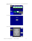
Continuous Loss-in-Weight Blenders Chapter 3: Installation 29
3-6 Set-up
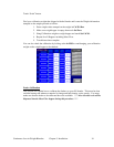
This section will discuss the mechanical setup and control system setup of the continuous
loss-in-weight blending system. After reading this section, you should be familiar with the
mechanical setup and the electronic control setup of the blending system.
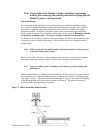
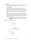
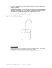
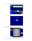
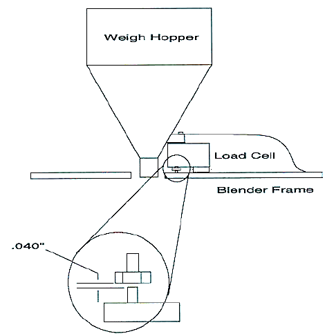
Load Cell Adjustment
The mechanical setup of the continuous loss-in-weight blending system involves the
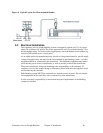
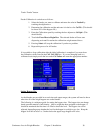
adjustment of the weigh hopper load cells (Please refer to the figure below). This figure
illustrates the proper adjustment of the load cell mechanical stop bolt. The setting for the
positive stop is necessary to prevent the load cell from being “over-ranged” by excessive
loading on the weigh hopper. The setting for the load cell stop is forty thousandths of an inch
maximum (.040”). This should be set by a feeler thickness gauge with the weigh hopper
empty.
If a feeler gauge is not available, the weigh hopper should be filled with the material that is to
be blended, and the stop adjusted so there is just a very small gap (a couple of sheets of
notebook paper) between the load cell, and the blender base stop. This will allow the load cell
to operate without mechanical restrictions and provide an overload safety. To adjust the stop,
adjust the screw located on the bottom of the load cell. Adjust the screw up to increase the
gap and down to decrease the gap.
Note: THE WEIGH HOPPER ASSEMBLY MUST BE FREE FROM FRICTION,
WITH NO MECHANICAL OBSTRUCTIONS OTHER THAN THE LOAD
CELL ITSELF.
Figure 10: Load Cell Mechanical Stop Adjustment